
Precision die casting surface treatment device with damage repair function

A surface treatment device and damage repair technology, applied in the field of surface treatment devices for precision die-casting parts, can solve problems such as poor treatment effect, multiple dead angles, and internal stress concentration of die-casting parts, so as to improve repair stability, intelligently adjust repair amount, The effect of increasing the contact area

Active Publication Date: 2021-12-21
江苏中科云控智能工业装备有限公司
View PDF10 Cites 0 Cited by
  • Summary
  • Abstract
  • Description
  • Claims
  • Application Information

AI Technical Summary

Problems solved by technology

The traditional surface treatment device for die-casting parts is not effective for such tubular printed die-casting parts. The printing process requires high precision and the printing structure is complicated. The traditional surface treatment method will have many dead angles, and it is impossible to process the die-casting process. Removal of impurities, protrusions, burrs, etc. attached to the surface of the workpiece
Some equipment will use thermal explosion to surface treat complex workpieces, but the hot explosion gas is easy to mix fly dust particles, and fly dust particles are easy to embed inside the die casting during the thermal explosion process, and the embedding of impurity particles can easily lead to die castings Stress concentration occurs inside, reducing the service life of die castings
On the other hand, the thermal explosion surface treatment method has limited treatment effect on the inner tube wall of tubular die-casting parts, and it is easy to produce dead ends in treatment.
Traditional die casting surface treatment devices lack damage repair function, and the treated die castings are prone to NG

Method used


Image

  • Precision die casting surface treatment device with damage repair function
  • Precision die casting surface treatment device with damage repair function
  • Precision die casting surface treatment device with damage repair function

Examples


Embodiment Construction

[0024] The following will clearly and completely describe the technical solutions in the embodiments of the present invention with reference to the accompanying drawings in the embodiments of the present invention. Obviously, the described embodiments are only some, not all, embodiments of the present invention. Based on the embodiments of the present invention, all other embodiments obtained by persons of ordinary skill in the art without making creative efforts belong to the protection scope of the present invention.

[0025] see Figure 1-9 , the present invention provides technical solutions:

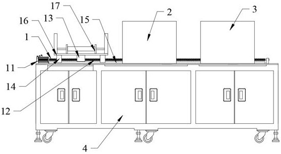
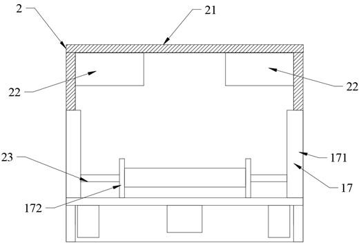
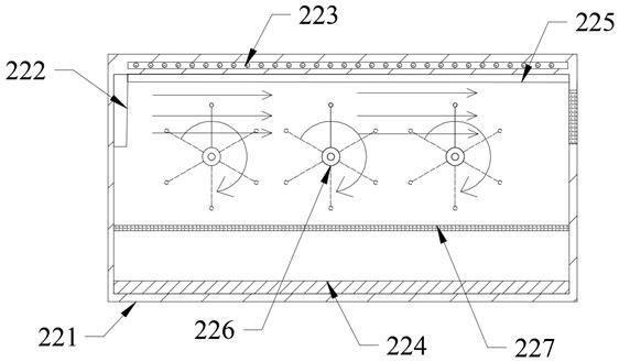
[0026] Such as Figure 1-9 As shown, a precision die casting surface treatment device with damage repair function, including transfer assembly 1, surface treatment assembly 2, damage repair assembly 3, lower frame 4, transfer assembly 1, surface treatment assembly 2, damage repair assembly 3 and the upper surface of the lower frame 4 are firmly connected, and the transfer assembly...


PUM


Abstract

The invention discloses a precision die casting surface treatment device with a damage repair function, and relates to the technical field of die casting surface treatment. The precision die casting surface treatment device comprises a transfer assembly, a surface treatment assembly, a damage repair assembly and a lower frame, the transfer assembly, the surface treatment assembly and the damage repair assembly are fixedly connected with the upper surface of the lower frame; and the transfer assembly penetrates through the surface treatment assembly and the damage repair assembly. According to the precision die casting surface treatment device, automatic station conversion is achieved in the machining process of a die casting through the transfer assembly, manual participation is avoided, and the probability of safety accidents in the workpiece machining process can be reduced. Self-circulation of rotation of metal balls is achieved through a gas inlet unit, the contact area between the metal balls and external input gas is increased, the states of the metal balls are switched through switching of the rotation angle, and directional carrying of impurity particles is achieved.

Description

technical field [0001] The invention relates to the technical field of die casting surface treatment, in particular to a precision die casting surface treatment device with damage repair function. Background technique [0002] Die casting is produced by pouring liquid copper, zinc, aluminum, aluminum alloy, etc. into the feed port of the die casting machine, and forming the workpiece through the casting mold. Die-casting parts can produce various special-shaped parts. In industrial production, tubular die-casting parts with printing are a kind of die-casting parts with high requirements. The stamping of the KN95 mask is this type of die-casting. The traditional surface treatment device for die-casting parts is not effective for such tubular printed die-casting parts. The printing process requires high precision and the printing structure is complicated. The traditional surface treatment method will have many dead angles, and it is impossible to process the die-casting proce...

Claims


Application Information

Patent Timeline
IPC IPC(8): B08B7/00B08B9/032B08B15/02B22D31/00B23P6/00
CPCB08B7/0007B08B9/0328B08B15/02B22D31/002B23P6/00
Inventor 章明徐林森夏志杰于海龙
Owner 江苏中科云控智能工业装备有限公司
Learn More