
Photon neural network

A neural network and photonic technology, applied in the field of photonic neural network, can solve the problems of different input/output, low computing accuracy of neural network, limiting the computing accuracy of photonic neural network, etc., to reduce the number and eliminate calculation errors.

Pending Publication Date: 2021-12-17
UNITED MICROELECTRONICS CENT CO LTD
View PDF0 Cites 3 Cited by
  • Summary
  • Abstract
  • Description
  • Claims
  • Application Information

AI Technical Summary

Problems solved by technology

Therefore, performance differences between modulators / detectors may cause different input / output after the same signal passes through
Especially for high-precision calculations, the impact of this difference will be greater
For example, when the performance difference between modulators / detectors connected to different channels of the photonic neural network is greater than 1%, the operational accuracy of the neural network will be lower than 6bit
This greatly limits the computational accuracy of photonic neural networks

Method used


Image

  • Photon neural network
  • Photon neural network
  • Photon neural network

Examples


Embodiment Construction

[0036] Embodiments of the present disclosure will be described in more detail below with reference to the accompanying drawings. Although certain embodiments of the present disclosure are shown in the drawings, it should be understood that the disclosure may be embodied in various forms and should not be construed as limited to the embodiments set forth herein; A more thorough and complete understanding of the present disclosure. It should be understood that the drawings and embodiments of the present disclosure are for exemplary purposes only, and are not intended to limit the protection scope of the present disclosure.

[0037] It should be understood that the various steps described in the method implementations of the present disclosure may be executed in different orders, and / or executed in parallel. Additionally, method embodiments may include additional steps and / or omit performing illustrated steps. The scope of the present disclosure is not limited in this respect. ...


PUM


Abstract

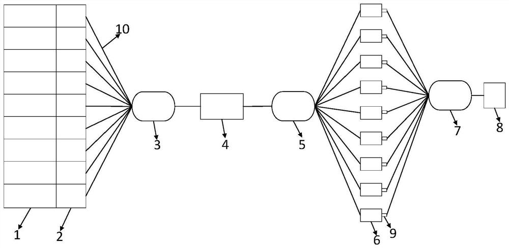
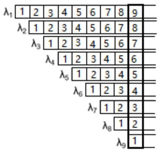
The invention provides a photon neural network. The photon neural network comprises a laser array, a modulator array, a first beam combiner, a modulator, a beam splitter, a delay line, a second beam combiner and a detector, the laser array emits a plurality of laser beams with different wavelengths; the modulator array modulates the laser output by the laser array, and loads the weight of the convolution kernel to the light emitted by the laser array; the first beam combiner combines the modulated multiple laser beams to obtain a first light beam; the modulator modulates the first light beam and loads to-be-processed information to the first light beam; the beam splitter splits the first light beam loaded with the to-be-processed information to obtain a plurality of light beams with different wavelengths; the delay line enables the split multiple beams of light to generate equal difference delay; the second beam combiner combines the multiple beams of light after the equal difference time delay is generated to obtain a second light beam; and the detector receives the second light beam to realize dislocation addition of the signals. The number of control circuits is reduced, and meanwhile calculation errors caused by performance differences are eliminated.

Description

technical field [0001] The invention relates to the field of integrated photons, in particular to a photon neural network. Background technique [0002] In recent years, artificial intelligence technology has penetrated into all aspects of our social life. Especially in the past ten years, the computing scale of artificial intelligence technology has become larger and larger, and its dependence on hardware has also become higher and higher. According to the statistics of OpenAI, an artificial intelligence research organization, the amount of floating-point calculations of deep artificial neural networks has grown at an alarming rate from 2012 to 2020, doubling about every 3-4 months, far exceeding the growth rate of Moore's Law for integrated circuits. At the same time, Moore's Law has gradually approached the physical limit of semiconductor technology and the limitation of microelectronic technology manufacturing process, and is facing the problem of failure. Since more t...

Claims


Application Information

Patent Timeline
IPC IPC(8): G06E1/00G06N3/04
CPCG06E1/00G06N3/045Y02D10/00
Inventor 刘胜平田野李强赵洋王玮
Owner UNITED MICROELECTRONICS CENT CO LTD
Learn More