
In-situ stretching multi-photon laser confocal imager and method for real-time in-situ three-dimensional observation of internal structure of blended polymer

A laser confocal and polymer blending technology, which is applied in optics, instruments, optical components, etc., can solve problems such as misunderstanding of the true form of two-dimensional image information

Inactive Publication Date: 2021-12-17
JILIN UNIV
View PDF11 Cites 0 Cited by
  • Summary
  • Abstract
  • Description
  • Claims
  • Application Information

AI Technical Summary

Problems solved by technology

Images obtained by these techniques provide information about 2D hybrid morphology, but the lack of 3D information is likely to lead to misinterpretation of true morphology by 2D image information

Method used


Image

  • In-situ stretching multi-photon laser confocal imager and method for real-time in-situ three-dimensional observation of internal structure of blended polymer
  • In-situ stretching multi-photon laser confocal imager and method for real-time in-situ three-dimensional observation of internal structure of blended polymer
  • In-situ stretching multi-photon laser confocal imager and method for real-time in-situ three-dimensional observation of internal structure of blended polymer

Examples


Embodiment 1

[0059] After mixing 0.8g of polypropylene, 0.2g of polystyrene and 100mL of toluene solvent, add 0.01g of TB under the condition of stirring, drop the obtained mixed solution on the polarizer, and heat at 180°C for 10min to remove the toluene solvent Finally, the temperature was lowered to room temperature at a cooling rate of 1°C / min, 10°C / min and 50°C / min, respectively, to prepare a blended polymer sample containing a fluorescent probe;

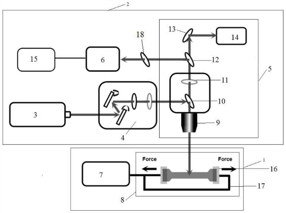
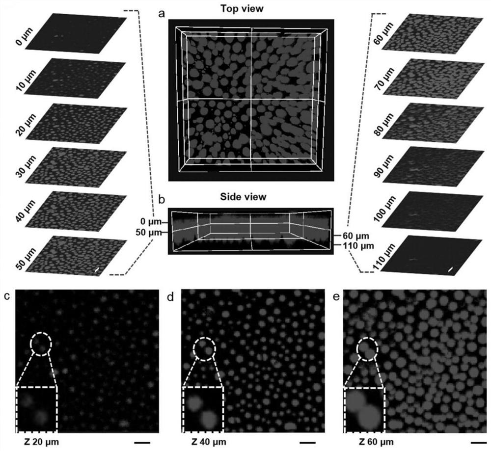
[0060] The blended polymer sample is placed on an adjustable automatic tensile testing machine 1 without stretching, and the femtosecond laser 3 emits a laser with a wavelength of 800 nm, which passes through the scanning part 4 in sequence and is under the control of the software. The objective lens of the optical microscope 5 is moved down along the direction perpendicular to the blended polymer, so that the laser light emitted by the femtosecond laser 3 is focused on the surface of the blended polymer sample 50 away from the fluorescent p...

Embodiment 2

[0067] After mixing 0.8g polypropylene, 0.2g polystyrene and 0.01g TB, blending (blending temperature is 180°C and time is 10min), granulation and injection (temperature is 180°C) in sequence to prepare A 6cm long, 1cm wide, and 0.5cm thick dumbbell-shaped polymer blend sample containing a fluorescent probe;

[0068] The blended polymer sample containing the fluorescent probe is placed on the adjustable automatic tensile testing machine 1, the tensile speed of the adjustable automatic tensile testing machine is set to be 15mm / min, and the femtosecond laser 3 A laser with a wavelength of 800nm ​​is emitted, which passes through the scanning part 4 in sequence and the objective lens of the optical microscope 5 is moved down along the direction perpendicular to the blended polymer under the control of the software, so that the laser emitted by the femtosecond laser 3 Focusing on the surface of the blended polymer sample containing fluorescent probes below 50 micrometers, using Z-...


PUM

PropertyMeasurementUnit
wavelengthaaaaaaaaaa

Abstract

The invention relates to the technical field of in-situ imaging, in particular to an in-situ stretching multi-photon laser confocal imager and a method for real-time in-situ three-dimensional observation of an internal structure of a blended polymer. The invention provides an in-situ stretching multi-photon laser confocal imager which comprises an adjustable automatic tensile testing machine (1) and an imaging device (2); the imaging device (2) comprises a femtosecond laser (3), a scanning part (4), an optical microscope (5) and a CCD sensor (6) which are connected in sequence. The in-situ stretching multi-photon laser confocal imager can realize real-time in-situ three-dimensional observation of internal structures of more than two different polymers.

Description

technical field [0001] The invention relates to the technical field of in-situ imaging, in particular to an in-situ stretching multiphoton laser confocal imager and a method for real-time in-situ three-dimensional observation of the internal structure of a blended polymer. Background technique [0002] Matter is the basis for the progress and development of human society. Due to its rich sources, low density, corrosion resistance and low energy consumption, polymer materials have been widely used in various fields of the national economy, including industry, agriculture, transportation, communication and even daily life, and have become the first after wood, steel and cement. Four major materials. In order to meet the needs of new technologies and applications, researchers need to develop new materials with unique and excellent properties as soon as possible. However, chemically synthesized new materials have disadvantages such as high cost and long cycle time, which are n...

Claims


Application Information

Patent Timeline
Patent Type & Authority Applications(China)
IPC IPC(8): G02B21/16G02B21/10G02B21/36G02B21/24
CPCG02B21/16G02B21/10G02B21/361G02B21/241
Inventor 徐斌武志远田文晶
Owner JILIN UNIV
Learn More