
Turbotype electrical respirator

A ventilator and turbine-type technology, applied in the field of ventilators, can solve problems such as difficulty in achieving oxygen concentration, air flow, difficulty in precise control of oxygen flow, large flow rate and flow of mixed gas, and achieve the effect of ensuring accurate oxygen concentration

Inactive Publication Date: 2010-06-09
BEIJING AEONMED
View PDF5 Cites 25 Cited by
  • Summary
  • Abstract
  • Description
  • Claims
  • Application Information

AI Technical Summary

Problems solved by technology

The disadvantage of this ventilator is: because oxygen adopts high-pressure oxygen, the high-pressure flow often causes damage to the turbine, and if the turbine is damaged from the impact of high-pressure gas, the flow rate of high-pressure oxygen must be limited. When high oxygen concentration flow rates are required, the patient cannot receive high concentrations of oxygen
In fact, it is difficult for this type of ventilator to even reach an oxygen concentration above 80%, which limits its use
Moreover, in the use of this ventilator, often, the flow rate and flow rate of the mixed gas after the air-oxygen mixture is very large, and a part of the mixed gas cannot be inhaled to the inhalation end through the turbine. Therefore, the precise control of the air flow and oxygen flow Very difficult, and in fact often requires corrections in the algorithm

Method used


Image

  • Turbotype electrical respirator
  • Turbotype electrical respirator
  • Turbotype electrical respirator

Examples


Embodiment Construction

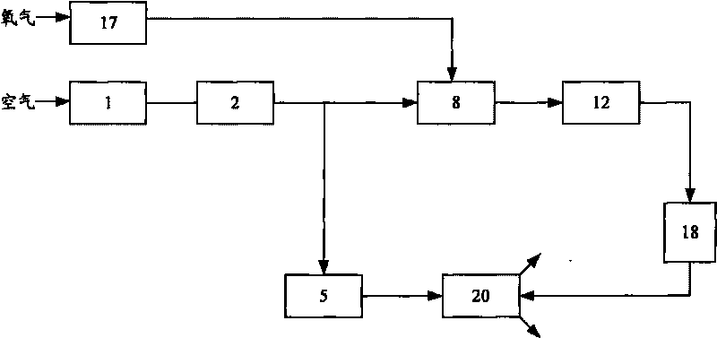
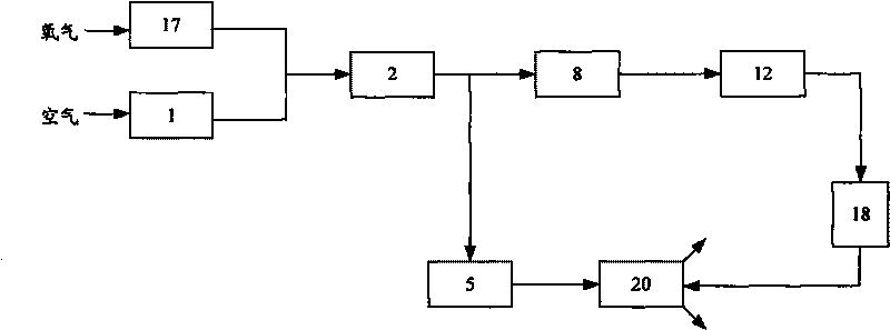
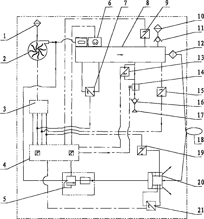
[0017] figure 2 A structural module diagram of the turbo electric ventilator 100 according to an embodiment of the present invention is shown, wherein only main structural modules are shown for the sake of clarity. see figure 2 It can be seen that the turbine electric ventilator 100 of this embodiment mainly includes: an air inlet 1; a microturbine 2, which sucks the air entering through the air inlet 1 into the ventilator 100; an oxygen inlet 17, which provides high-pressure oxygen to the ventilator 100 ; the air-oxygen mixing chamber 8, the air sucked by the turbine 2 and the high-pressure oxygen provided via the oxygen inlet are thoroughly mixed in this chamber 8; Port 18 communicates to provide the patient with an inhalable gas mixture. In order to form a complete air circuit, this figure also shows the structural modules that constitute the exhalation circuit. A part of the low-pressure air sucked into the air-oxygen mixing chamber 8 by the microturbine 2 reaches the ...


PUM


Abstract

The invention provides a turbotype electrical respirator comprising an air inlet (1), a turbine (2), an oxygen inlet (17), an air-oxygen mixing chamber (8) and a suction end (12), wherein the turbine (2) sucks the air entering from the air inlet (1); the air-oxygen mixing chamber (8) is used for mixing the air sucked by the turbine (2) and the oxygen supplied by the oxygen inlet (17); the suction end (12) is communicated with the air-oxygen mixing chamber (8) so as to convey the mixed gas to a terminal (18). The electrical respirator is characterized in that the oxygen inlet (17) is directly communicated with the air-oxygen mixing chamber (8). According to the invention, the turbine is not damaged by the electrical respirator and the mixed gas with high oxygen concentration can be acquired at a patient end, the flow rate of air and oxygen can be controlled by using a simple method and the precise oxygen concentration of the mixed gas which is input to the terminal, i.e. the patient end, can be ensured.

Description

technical field [0001] The present invention relates to a ventilator in the medical field, and more particularly, to a turbine electric ventilator. Background technique [0002] Among the existing ventilators, pneumatic electronically controlled ventilators account for the vast majority of the market share, but this type of ventilator requires a compressed air source, which is inconvenient in remote areas or in the case of field first aid , either bulky, or limited gas source and limited use time. In recent years, some electric ventilators have appeared, which can work without a compressed air source, such as cylinder-piston type, bellows airbag type, micro-pump micro-turbine electric ventilator. Among them, the micropump microturbine electric ventilator is ideal because of its small size and relatively low cost. At present, the micro-turbine electric ventilator that can be used for treatment on the market is mainly imported, and this ventilator adopts the method of mixing...

Claims


Application Information

Patent Timeline
IPC IPC(8): A61M16/00
Inventor 颜辉
Owner BEIJING AEONMED
Learn More