
Electromagnetic valve with anti-interference function

A solenoid valve and anti-interference technology, which is applied in the field of solenoid valves, can solve problems such as device leakage, internal valve structure wear, and device influence on normal use of the device, achieving the effect of improving stability and sealing

Pending Publication Date: 2021-12-17
深圳市宽田科技有限公司
View PDF1 Cites 0 Cited by
  • Summary
  • Abstract
  • Description
  • Claims
  • Application Information

AI Technical Summary

Problems solved by technology

[0004] 1. The comparative document CN110081186A discloses an isolated lever solenoid valve, which relates to the technical field of solenoid valves, including: "the main valve body, the outlet end cover, the upper valve cover, the lever sealing assembly and the electromagnetic drive device, and the main valve body is equipped with There is an inlet and a sealing chamber, an outlet and a valve port are provided on the outlet end cover, and the valve port extends into the sealing chamber, and an empty chamber and an electromagnetic interface are provided on the upper valve cover. The lever sealing assembly includes a valve port seal, an isolation seal, The lever support plate and the pole; the electromagnetic drive device is fixed on the upper valve cover through the electromagnetic interface, and the electromagnetic drive device includes the solenoid valve body, the movable and telescopic iron core set in the solenoid valve body, and the solenoid valve body and used Because of the spring that pushes the iron core out, when the fluid enters the solenoid valve, no matter it is in the open state or closed state, the fluid will not enter the upper valve cover end, that is, the fluid and the electromagnetic drive device are completely isolated, which can be well reduce the influence of the fluid on the electromagnetic drive device", but when the device is in use, the internal electromagnetic control device is often subject to external electromagnetic interference, and the electromagnetic interference will directly affect the flow control of the internal current, and frequent interruptions In the case of flow or automatic switch, there will also be delays, etc. The external electromagnetic interference will greatly affect the control of the valve by the internal electromagnetic control device, which is not conducive to the use of the device by the staff.
[0005] 2. When the existing electromagnetic valve device is in use, there is usually a set of valve structures installed inside. Due to the long-term use of the device, the internal valve will produce friction during use, and the friction will cause the internal valve structure to wear out. After wear and tear, there will be a gap between the valve structure and the inner side, which will cause water leakage in the device even if the valve is closed. When the staff is repairing the pipeline, the internal water seepage will greatly affect the maintenance of the device by the staff. Unfavorable for staff to use the device
[0006] 3. When the existing electromagnetic valve device is in use, internal damage or other problems often occur, so the staff needs to maintain and overhaul the device frequently. When performing maintenance and overhaul on the electromagnetic valve, it is usually necessary to use auxiliary tools to repair the device. When the bolts at the top connection are disassembled, when there are many valves that the staff need to check, the bolts at the valve connection will greatly affect the efficiency of the staff's maintenance, and it will take a long time to disassemble the device, not only It will affect the maintenance of the staff and at the same time affect the efficiency of production
[0007] 4. When the existing electromagnetic valve device is not used for a long time, and the external temperature is low, it is likely to cause the device to freeze. Since the device is a movable structure at the joint, the icing will directly block the flow of the internal liquid , and the forcible use of electromagnetic valves is likely to cause damage to the internal device due to high stress, and damage to the device will affect the normal use of the device. Even if the ice at the connection is melted, it will still freeze at one end of the time. situation, which greatly affects the staff's use of the device

Method used


Image

  • Electromagnetic valve with anti-interference function
  • Electromagnetic valve with anti-interference function
  • Electromagnetic valve with anti-interference function

Examples


Embodiment 1

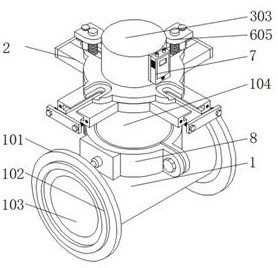
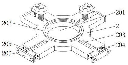
[0037] Embodiment 1: including the valve body 1 and the connecting plate 2, the top of the valve body 1 is installed with a tee pipe 104, the front and back of the valve body 1 are installed with a mounting plate 101, and the front of the mounting plate 101 is equipped with a sealing ring 102 , the inner side of the mounting plate 101 is provided with a water outlet 103, and the inside of the valve body 1 is equipped with an inclined surface 105. The valve body 1 is the main bearing structure of the device, which can provide an installation position for the device on the top, and at the same time can ensure the overall safety of the device. Stability, the tee pipe 104 can provide the installation position for the electromagnetic valve device on the top, to ensure the normal use of the electromagnetic valve device on the top, the installation plate 101 can be connected with the external pipeline, to ensure that the device can be installed and used normally, and the sealing ring 1...

Embodiment 2

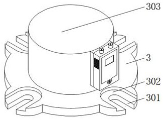
[0039] Embodiment 2: Comprising a combination disk 3, a mounting plate 701 is installed on one side of the combination disk 3, an anti-jamming device 7 is installed on one side of the mounting plate 701, and an anti-jamming device 7 is installed on one side of the mounting plate 701. The front of the jammer 7 is provided with a cooling port 702, the top of the anti-jammer 7 is installed with two sets of data interfaces 703, one side of the anti-jammer 7 is movably installed with a front cover 704, and one side of the front cover 704 is embedded with an observation port 705, one side of the front cover 704 is penetrated with screws 706, and the mounting plate 701 can directly install the anti-jamming device 7 on one side of the top shell 303 to ensure the stability of the anti-jamming device 7, and the anti-jamming device 7 can effectively Provide electromagnetic anti-interference for the inside of the device, and prevent the device from being uncontrollable due to electromagnet...

Embodiment 3

[0041] Embodiment 3: including a three-way pipe 104, a flow frame 503 is installed on the inner side of the three-way pipe 104, a movable valve 5 is installed on the inner side of the flow frame 503, and a transmission rod 501 is installed on the bottom of the movable valve 5, and the transmission rod 501 The bottom of the flow frame 503 is provided with a secondary valve 502, the outer surface of the flow frame 503 is provided with a flow hole 504, the outside of the bottom of the flow frame 503 is provided with a drain hole 505, the outside of the flow frame 503 is provided with a water inlet 506, and the flow frame 503 can be used for The inner solenoid valve device provides the installation position and can provide restriction for the internal water flow to ensure the normal use of the device. The movable valve 5 can be lifted and lowered by the control of the top electromagnetic device to ensure that the device can normally control the switch. The transmission rod 501 can m...


PUM


Abstract

The invention discloses an electromagnetic valve with the anti-interference function, which comprises a valve body and a connecting disc, wherein a three-way tube is mounted at the top of the valve body, the connecting disc is mounted at the top of the three-way tube, a wiring cover is mounted in the connecting disc, and a combined disc is mounted at the top of the connecting disc; a mounting plate is mounted on one side of the combined disc, an anti-jamming device is mounted on one side of the mounting plate, and four groups of sliding plates are movably mounted on the outer side of the connecting disc; a flowing frame is mounted on the inner side of the three-way tube, a movable valve is movably mounted on the inner side of the flowing frame, and a heat transfer piece is mounted on the outer side of the three-way tube. By mounting the anti-jamming device, the problem that a traditional device cannot be controlled due to the fact that the traditional device is easily influenced by the outside when being used is effectively solved.

Description

technical field [0001] The invention relates to the technical field of electromagnetic valves, in particular to an electromagnetic valve with an anti-interference function. Background technique [0002] With the development of the times, people need to use valve devices in daily life or factory processing to control the flow of pipeline liquid. Most of the traditional valves are manual valves. However, because manual valves require manpower to control, people have found that traditional valves are very inappropriate for a long time. Convenient, unable to open and close the time setting, and the poor sealing of the valve often causes water leakage, so electromagnetic valves gradually enter people's production and life. Electromagnetic valves can effectively solve the problems of traditional valves and are convenient for users. device is used, but there are deficiencies in the traditional electromagnetic valve device and need to be improved. [0003] The defective that electr...

Claims


Application Information

Patent Timeline
Patent Type & Authority Applications(China)
IPC IPC(8): F16K31/06F16K49/00F16K51/00
CPCF16K31/0675F16K49/002F16K51/00
Inventor 闫贞阳周全肖育为
Owner 深圳市宽田科技有限公司
Learn More