
Aortic valve composite implant valve system and using method

A technology for aorta and valves, applied in the direction of heart valves, valve rings, balloon catheters, etc., can solve the problem of unstable valve stent fixation, and achieve the effect of reducing the risk of falling off, firm fixation effect, and equal force

Pending Publication Date: 2021-12-17
范卫东
View PDF0 Cites 0 Cited by
  • Summary
  • Abstract
  • Description
  • Claims
  • Application Information

AI Technical Summary

Problems solved by technology

[0006] The purpose of the present invention is to provide an aortic valve composite implanted valve system and its use method, to solve the problem that the valve support is not firmly fixed when the patients with aortic valve insufficiency are treated with TAVR

Method used


Image

  • Aortic valve composite implant valve system and using method
  • Aortic valve composite implant valve system and using method
  • Aortic valve composite implant valve system and using method

Examples


Embodiment 1

[0037] The following is a detailed explanation of the present invention in conjunction with the specific drawings, such as figure 1 As shown, the valve stent 1 used in this embodiment is roughly the same as the current common stent design, and is divided into upper and lower ends. The diameter of the lower stent 13 is smaller than that of the upper stent 11, but the difference from the existing stent is that, The valve stent 1 designed in this embodiment is provided with a connecting fixed section 12 between the upper stent 11 and the lower stent 13.

[0038] like figure 1 As shown, the diameter of the fixation segment 12 is smaller than the diameter of the lower segment support 13, and is the thinnest among the three parts of the valve support 1. Specifically, the radius of the fixation segment 12 is smaller than that of the lower segment support 13 by 1 to 2 mm; The diameter of the fixing segment 12 is smaller than the diameter of the upper and lower parts, so the valve ste...

Embodiment 2

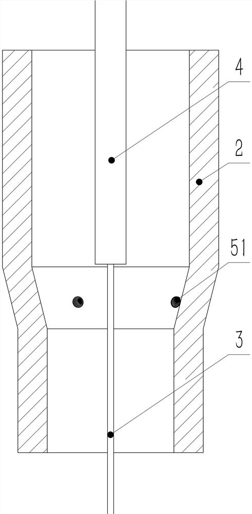
[0045] This embodiment is not substantially different from the technical solutions used in the above-mentioned embodiments, and the main difference is that: this embodiment is an alternative solution when the patient's native valve does not have a memory material fixing nail 51, and a sclerosing agent is used instead of the memory material. Material for fixing nails.

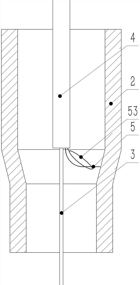
[0046] like Image 6 As shown, after completing the setting of the guide wire 3 and the catheter 4 according to the method of the above embodiment, the sclerosing agent catheter 9 is inserted into the aortic sinus of the patient along the catheter 4; the sclerosing agent catheter 9 can send the sclerosing agent from the nozzle. , and the hardener is filled in such as Figure 5 The appropriate fixation point 52 in the middle; the sclerosing agent will be adsorbed on the valve, and will harden rapidly after contacting body temperature, forming a firm sclerosing agent fixing nail 91, such as Figure 7 shown.

[...


PUM


Abstract

The invention relates to the field of medical instruments, in particular to an aortic valve composite implant valve system and a using method. The aortic valve composite implant valve system comprises a valve stent; the valve stent is divided into an upper section and a lower section, and a fixing section with a groove is arranged between the upper section and the lower section; and a fixing nail is arranged at the joint of every two aortic valves, and the fixing nails are matched with the fixing sections so that the valve stent can be firmly fixed to the original aortic valve, so that a new bioprosthetic valve is formed. According to the invention, a memory material or a hardening agent is adopted as the material of the fixing nails, the fixing nails are easy to set and firmer, compared with an existing artificial aortic valve stent, the valve fixing method is more difficult to fall off, and the problem that a bioprosthetic valve is difficult to fix for a patient suffering from valve insufficiency is solved.

Description

technical field [0001] The invention belongs to the field of medical devices, in particular to a system and method for compound implantation of an aortic valve. Background technique [0002] The aortic valve is located between the left ventricle and the ascending aorta and acts as a one-way valve to prevent blood from refluxing from the aorta back to the left ventricle; if the aortic valve is diseased, its function will be lost, For example: the heart does not fully open during systole (stenosis), making it difficult to eject blood from the left ventricle; or the aortic valve does not fully close during diastole (regurgitation), allowing blood from the ascending aorta to flow back into the left ventricle; Arterial valve stenosis or insufficiency will affect heart function, reduce heart function, and then lead to insufficient blood supply to the whole body, causing patients to have a variety of adverse reactions, and even lead to new functional failure, fainting, cardiogenic ...

Claims


Application Information

Patent Timeline
IPC IPC(8): A61F2/24
CPCA61F2/2409A61F2/2412A61F2/2418A61F2/2427A61F2/2433A61F2/243A61F2/2442A61F2/2466
Inventor 范卫东
Owner 范卫东
Learn More