Eureka AIR delivers breakthrough ideas for toughest innovation challenges, trusted by R&D personnel around the world.

Machining method for PMI foam filling part

A processing method and foam filling technology, applied in the field of process heads, can solve the problems of milling broken parts, easy milling missing parts, parts deformation, etc., and achieve the effects of reducing part deformation, convenient clamping, and uniform surface allowance.

Pending Publication Date: 2021-12-10
成都凯迪精工科技有限责任公司
View PDF6 Cites 0 Cited by
  • Summary
  • Abstract
  • Description
  • Claims
  • Application Information

AI Technical Summary

Problems solved by technology

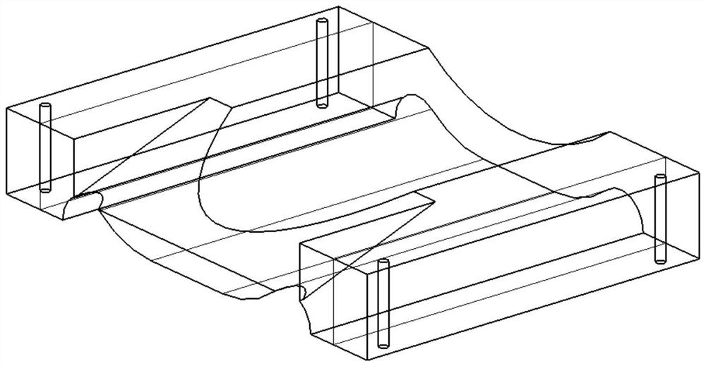
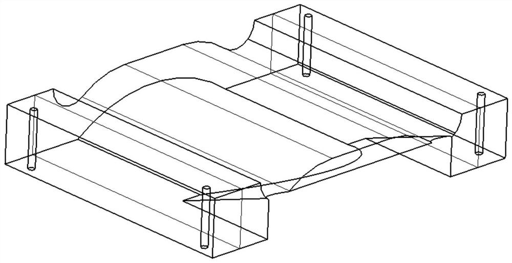
[0006] The purpose of the present invention is to provide a processing method for PMI foam-filled parts, to solve the problems that PMI foam-filled parts are prone to indentation when clamping, resulting in deformation of parts, easy milling of missing parts, milling parts and other problems during processing

Method used


Image

  • Machining method for PMI foam filling part
  • Machining method for PMI foam filling part
  • Machining method for PMI foam filling part

Examples


Embodiment 1

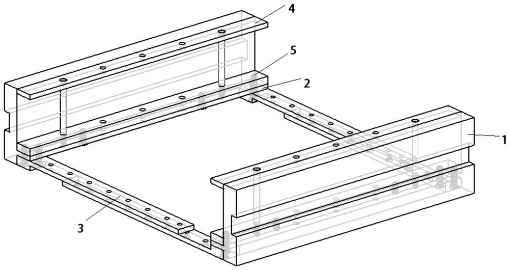
[0038] see Figure 3 to Figure 8 As shown, this embodiment provides a process head for processing PMI foam-filled parts, including two process head side stops 1 oppositely arranged. The process head side stop 1 is 300 mm long, 40 mm wide, and 80 mm high. A weight-reducing groove 7 is provided on the side surface of the process head side block 1 facing away, and a support plate 2 is provided on the opposite side surface of the process head side block 1. The distance between the bottom surface of the support plate 2 and the bottom surface of the process head side block 1 is 10 mm. 2 The distance between the top surface and the top surface of the process head is 65mm, and several screw holes are arranged on the support plate 2.

[0039] A length-adjustable connection assembly is arranged between the two process head side stops 1, and the connection assembly includes two stacked adjustment plates 3, the length of which is 250 mm, the width of 20 mm, and the height of 10 mm. One e...


PUM


Abstract

The invention relates to the technical field of process heads, and provides a machining method of a PMI foam filling part. The machining method comprises the following steps of 1), clamping a blank piece by using a process head; 2), rough machining; 3), semi-finish machining; and 4), finish machining. The process head comprises two process head side baffles which are oppositely arranged, a length-adjustable connecting assembly is arranged between the two process head side baffles, the connecting assembly is used for adjusting the distance between the process head side baffles, each process head side baffle is provided with an adjustable clamping arm, each adjustable clamping arm comprises an upper strip-shaped pressing plate, a lower replacement base plate and an adjusting screw, the lower replacement base plates are fixed with the process head side baffles, and the upper strip-shaped pressing plates and the lower replacement base plates are in threaded connection with the upper ends and the lower ends of the adjusting screws. The problems that in the part machining process, due to irregular indentations, the datum plane of the part is uneven, due to the uneven datum plane, the molded surface and the mounting surface machined by the part are unqualified, and the machining efficiency and the machining qualification rate of PMI foam are affected are solved.

Description

technical field [0001] The invention relates to the technical field of process heads, in particular to a method for processing PMI foam-filled parts. Background technique [0002] PMI foam is a light, closed-cell, cross-linked rigid structural foam with high strength, high density, low density, 100% closed-cell structure and isotropy. At the same time, PMI foam has good mechanical properties, thermal deformation temperature and chemical stability, and has good compression creep properties, and is an ideal core material for high-performance sandwich structure composites. [0003] In daily processing, there are many PMI foams and easily deformable parts. In the processing of flutter models, the entire fuselage and wings are filled with PMI foam-filled parts, and their strength and weight have high requirements. It is necessary to ensure that the profile allowance of the processed PMI foam parts meets the requirements, and ensure that its weight is controlled within the allowa...

Claims


Application Information

Patent Timeline
Patent Type & Authority Applications(China)
IPC IPC(8): B26D7/01B26D3/00B23C3/00
CPCB26D7/01B26D3/00B23C3/00
Inventor 陈胜岳鹏田平陈泽蒲华重
Owner 成都凯迪精工科技有限责任公司
Why Eureka
Eureka Blog
Learn More