
A hand-held artificial pollination device for garden flowers and its application method

An artificial pollination, hand-held technology, applied in the field of garden flower planting, can solve the problems of uneven distribution, uneven pollen spraying, waste, etc., and achieve the effects of uniform pollination, uniform and stable pollination, and reduced waste.

Active Publication Date: 2022-03-22
HARBIN CITY ACAD OF AGRI SCI
View PDF11 Cites 0 Cited by
  • Summary
  • Abstract
  • Description
  • Claims
  • Application Information

AI Technical Summary

Problems solved by technology

[0005] (1) The pollen is sprayed through the adjustable pollination head. When the pollen is sprayed, the pollen moves and rushes out with the sprayed airflow, and cannot completely fall on the flowers. Some pollen will float around. Pollen is very precious, and it will be wasted if it is scattered around
[0006] (2) Because the front end of the adjustable pollination head needs to be close to the flowers, sometimes the dew on the flowers will stick to the adjustable pollination head. The contact between the dew and the pollen will cause the pollen to stick to the front end of the retractable pollination tube, resulting in poor pollen spraying. fluent
[0007] (3) The pollen is sprayed directly through the adjustable pollination head, and the distribution is uneven when sprayed
[0008] (4) The pollen is transported through the telescopic pollination tube. The outer wall of the telescopic pollination tube is a threaded structure, and the length can be adjusted by rotating and stretching. The adjustable range is small, and it is difficult to meet the actual needs.
[0009] (5) The whole device can only be held by the handle, which is inconvenient to operate

Method used


Image

  • A hand-held artificial pollination device for garden flowers and its application method
  • A hand-held artificial pollination device for garden flowers and its application method
  • A hand-held artificial pollination device for garden flowers and its application method

Examples


Embodiment 1

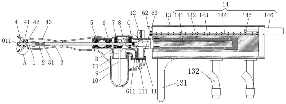
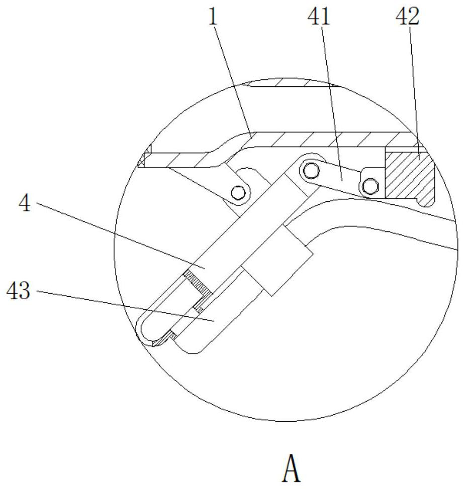
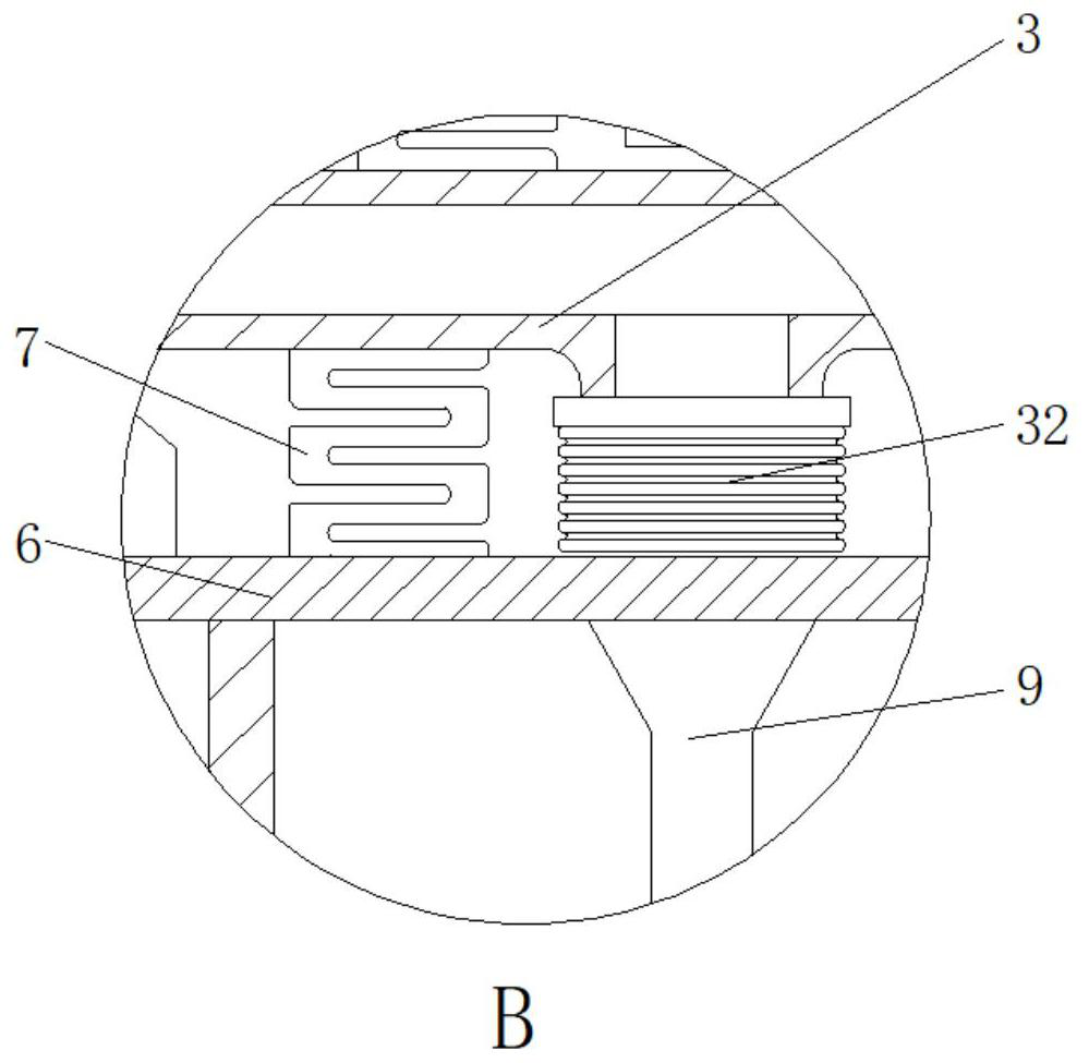
[0062] Such as Figure 1 - Figure 15 As shown, a hand-held garden flower artificial polishing device includes a rotary spray head 1, a suction nozzle 4 is provided on the four-week outer wall of the rotary spray head 1, and one end of the rotary spray head 1 is connected to transport The outer wall of the tube 3, one end of the conveying tube 3 is connected to the tube 6 through the spring strip 7, and the conveying motor 8 is provided on the conveying tube 3, and the delivery tube 3 is connected to one end of the spray head 1, and the outlet of the centrifuge fan 12 is connected, and centrifuged The inlet of the fan 12 is connected to the suction nozzle 4 through the trachea 43, and the transport tube 3 is connected to one side of the end of the centrifugal fan 12, and one end of the suction tube 9 is provided with a pollen cartridge 10.

[0063] By providing a suction nozzle 4 around the rotary spray head 1, it is possible to attract recycling to the floral flowers around the flo...

Embodiment 2

[0070] Such as Figure 1 - Figure 15 As shown, a hand-held garden flower artificial polishing device includes a rotary spray head 1, a suction nozzle 4 is provided on the four-week outer wall of the rotary spray head 1, and one end of the rotary spray head 1 is connected to transport The outer wall of the tube 3, one end of the conveying tube 3 is connected to the tube 6 through the spring strip 7, and the conveying motor 8 is provided on the conveying tube 3, and the delivery tube 3 is connected to one end of the spray head 1, and the outlet of the centrifuge fan 12 is connected, and centrifuged The inlet of the fan 12 is connected to the suction nozzle 4 through the trachea 43, and the transport tube 3 is connected to one side of the end of the centrifugal fan 12, and one end of the suction tube 9 is provided with a pollen cartridge 10.

[0071] The conveying tube 3 is fixed to both sides of the rotary spray head 1, respectively, and the side strips 31 and the rotary spray powder...

Embodiment 3

[0074] Such as Figure 1 - Figure 15 As shown, a hand-held garden flower artificial polishing device includes a rotary spray head 1, a suction nozzle 4 is provided on the four-week outer wall of the rotary spray head 1, and one end of the rotary spray head 1 is connected to transport The outer wall of the tube 3, one end of the conveying tube 3 is connected to the tube 6 through the spring strip 7, and the conveying motor 8 is provided on the conveying tube 3, and the delivery tube 3 is connected to one end of the spray head 1, and the outlet of the centrifuge fan 12 is connected, and centrifuged The inlet of the fan 12 is connected to the suction nozzle 4 through the trachea 43, and the transport tube 3 is connected to one side of the end of the centrifugal fan 12, and one end of the suction tube 9 is provided with a pollen cartridge 10.

[0075] An adhesive sleeve 5 is provided in one end cavity of the tube 6, and the rubber sleeve 5 can be used as a rubber material, and the rubb...


PUM


Abstract

The invention relates to the technical field of planting garden flowers, in particular to a hand-held artificial pollination device for garden flowers, which includes a rotary powder spray head, the outer walls of the rotary powder spray head are provided with suction nozzles, and the rotary powder spray head One end of the head is connected with a conveying pipe, and the outer wall of one end of the conveying pipe is connected with a pipe seat through a spring bar, and a vibration motor is arranged on the conveying pipe, and the end of the conveying pipe far away from the powder spraying head is connected with the outlet of a centrifugal fan, and the centrifugal fan The inlet of the inlet is connected with the suction nozzle through the trachea, and the side of the delivery pipe close to one end of the centrifugal fan is connected with a suction pipe, and one end of the suction pipe is provided with a pollen box. , It can attract and recover the pollen that escapes around the flowers during pollination, and re-enters the conveying pipe through the centrifugal fan, and sprays it from the rotary spraying head again, which greatly reduces the waste of pollen spraying pollination.

Description

Technical field [0001] The present invention relates to the field of garden floral planting, in particular a hand-held garden flower artificial polishing device and a method of use. Background technique [0002] Flowers are plants used to appreciate, have a variety of transformation, and there are many kinds of species. Typical flowers, on a limited grown short axis, raw calyx, petals and stamens and pistils that produce germ cells. Flowers are composed of corolla, calyx, flower support, flower, with a variety of colors, some grow a beautiful, fragrant; pollination is a plant junction result. There are usually some yellow powder in the flowers, which is called pollen. These pollen need to be passed to some of the plants. Pollen from the mobile process of the anthers to the position called pollination. [0003] China Patent Publication No. CN108552052A discloses a hand-held garden flower artificial polishing device, which discloses a hand-held garden flower artificial polishing ap...

Claims


Application Information

Patent Timeline
Patent Type & Authority Patents(China)
IPC IPC(8): A01H1/02
CPCA01H1/021A01H1/027
Inventor 刘志洋门万杰陈曦汪磊
Owner HARBIN CITY ACAD OF AGRI SCI
Learn More