Method for determining molybdenum alloy single crystal slip plane

A molybdenum alloy, plane technology, applied in the preparation of test samples, material analysis using wave/particle radiation, measurement devices, etc., can solve the problem of inaccurate determination of the lack of close packing of the single crystal of molybdenum alloy and the body-centered cubic structure. , the difficulty of sliding plane of single crystal materials, etc., to achieve the effect of improving the determination efficiency, high accuracy and easy operation

Inactive Publication Date: 2021-12-03
NORTHWEST INSTITUTE FOR NON-FERROUS METAL RESEARCH
View PDF1 Cites 0 Cited by
  • Summary
  • Abstract
  • Description
  • Claims
  • Application Information

AI Technical Summary

Problems solved by technology

[0003] Different crystal structures have different slip systems. The molybdenum alloy single crystal has a body-centered cubic structure, and the body-centered cubic slip plane is theoretically {110}. However, because the body-centered cubic structure lacks close-packed planes with sufficient close packing, The slip plane is not very sure, so in fact, the low temperature is {112}, the room temperature is {110}, and the high temperature is {123}. One or more slip planes slide along the same slip direction, resulting in corrugated slip bands on the surface of the sample, so it is very difficult to determine the slip plane of the single crystal material.
The traditionally used accumulative algorithm, mirror mapping method, and force axis index observation method cannot accurately determine the slip plane of the molybdenum alloy single crystal. planar approach

Method used


Image

  • Method for determining molybdenum alloy single crystal slip plane
  • Method for determining molybdenum alloy single crystal slip plane
  • Method for determining molybdenum alloy single crystal slip plane

Examples


Embodiment 1

[0024] The method for determining the sliding plane of a molybdenum alloy single crystal in this embodiment includes the following steps:

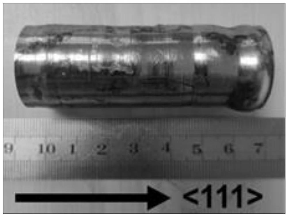
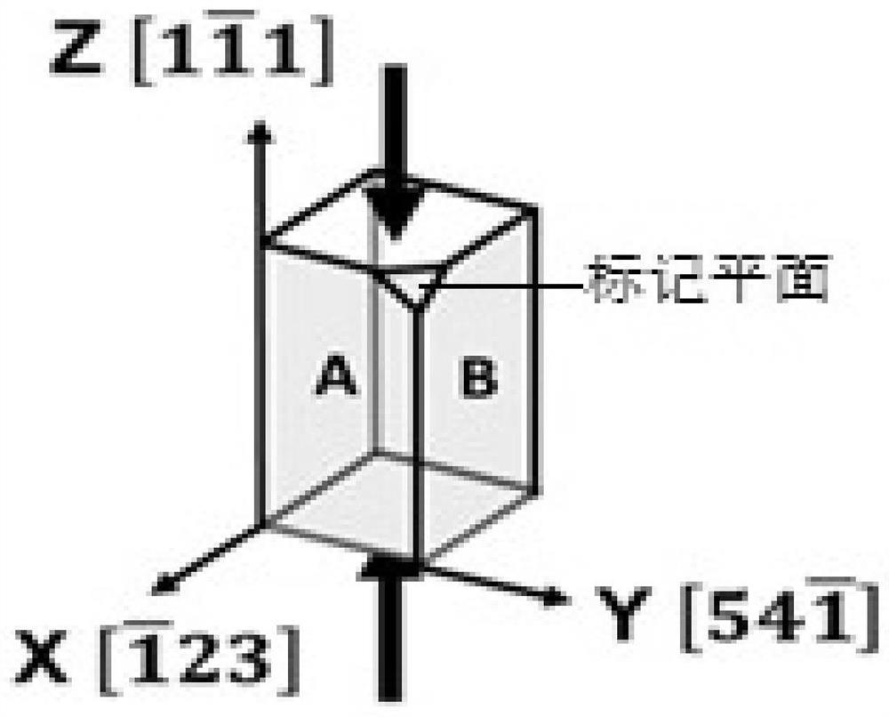
[0025] Step 1. Use wire cutting to cut out the sample on the Mo-3Nb alloy single crystal rod. The specific process is: first align the molybdenum wire used for wire cutting with the bottom surface of the Mo-3Nb alloy single crystal rod, and move along the Mo-3Nb alloy single crystal rod. The axial direction of the alloy single crystal rod starts to move the wire to obtain a cuboid sample with a length×width×height of 7mm×7mm×12mm, and then grinds a small plane at the upper right corner of the intersection vertex of the two sides of the sample As a marked plane; the Mo-3Nb alloy single crystal rod is prepared by the electron beam suspension zone melting method, and the crystal orientation is , such as figure 1 shown;

[0026] Step 2. Use the electron backscatter diffraction method (EBSD) to judge the crystal orientation of the side of the...


PUM


Abstract

The invention discloses a method for determining a molybdenum alloy single crystal slip plane, which comprises the following steps: cutting a sample on a molybdenum alloy single crystal rod by linear cutting, polishing a small plane at the intersection vertex of two side surfaces of the sample as a marking plane, determining the crystal orientation of the side surfaces of the sample, performing deformation treatment on the sample to obtain a deformed sample, analyzing the slip lines of the two adjacent side surfaces of the marked plane in the deformed sample, determining the included angle between the slip lines of the two adjacent side surfaces and the stress axis, and calculating by adopting a two-surface method to obtain the slip plane of the molybdenum alloy single crystal. The side crystal orientation of the molybdenum alloy sample is determined before deformation treatment of the molybdenum alloy sample, and the sliding lines after deformation of the two side surfaces are distinguished by grinding the marking planes at the intersection fixed points of the two side surfaces of the sample, so that measurement errors caused by sample deformation are avoided, the accuracy of measurement of the sliding plane after deformation of the molybdenum alloy single crystal is ensured, the operation is simple, consumed time is short and efficiency is high.

Description

technical field [0001] The invention belongs to the field of mechanical performance analysis of materials, and in particular relates to a method for determining the sliding plane of a molybdenum alloy single crystal. Background technique [0002] The plastic deformation modes of metals mainly include slip, twinning and kink, and the plastic deformation modes of crystal materials at room temperature are realized by slip. Determining the slip surface of crystals during deformation has important theoretical guiding significance for understanding the plastic deformation mechanism of materials and ensuring the safety of materials during service. [0003] Different crystal structures have different slip systems. The molybdenum alloy single crystal has a body-centered cubic structure, and the body-centered cubic slip plane is theoretically {110}. However, because the body-centered cubic structure lacks close-packed planes with sufficient close packing, The slip plane is not very s...

Claims


Application Information

Patent Timeline
Patent Type & Authority Applications(China)
IPC IPC(8): G01N21/84G01N1/28G01N1/32G01N23/203G01N23/20008
CPCG01N21/84G01N1/28G01N1/32G01N23/203G01N23/20008
Inventor 赵永庆焦奔奇张文胡忠武高选乔李延超殷涛辛甜郑晗煜裴雅
Owner NORTHWEST INSTITUTE FOR NON-FERROUS METAL RESEARCH
Why Eureka
Try Eureka