
Mud contact point monitoring device in submarine pipeline laying process and monitoring method

A submarine pipeline and monitoring device technology, which is applied in pipeline laying and maintenance, pipe laying ships, mechanical equipment, etc., can solve the problems of easy damage of cables and low efficiency of information transmission, and achieve enhanced motion stability and good transmission effect Effect

Active Publication Date: 2021-11-26
HARBIN ENG UNIV
View PDF11 Cites 0 Cited by
  • Summary
  • Abstract
  • Description
  • Claims
  • Application Information

AI Technical Summary

Problems solved by technology

[0006] The purpose of the invention is to solve the problem of low information transmission efficiency in the existing underwater cableless monitoring device for submarine pipeline laying, and the problem that the cable of the underwater cable monitoring device is easily damaged in complex sea areas, and then provide a Monitoring device and monitoring method for mud contact point during submarine pipeline laying

Method used


Image

  • Mud contact point monitoring device in submarine pipeline laying process and monitoring method
  • Mud contact point monitoring device in submarine pipeline laying process and monitoring method

Examples


specific Embodiment approach 1

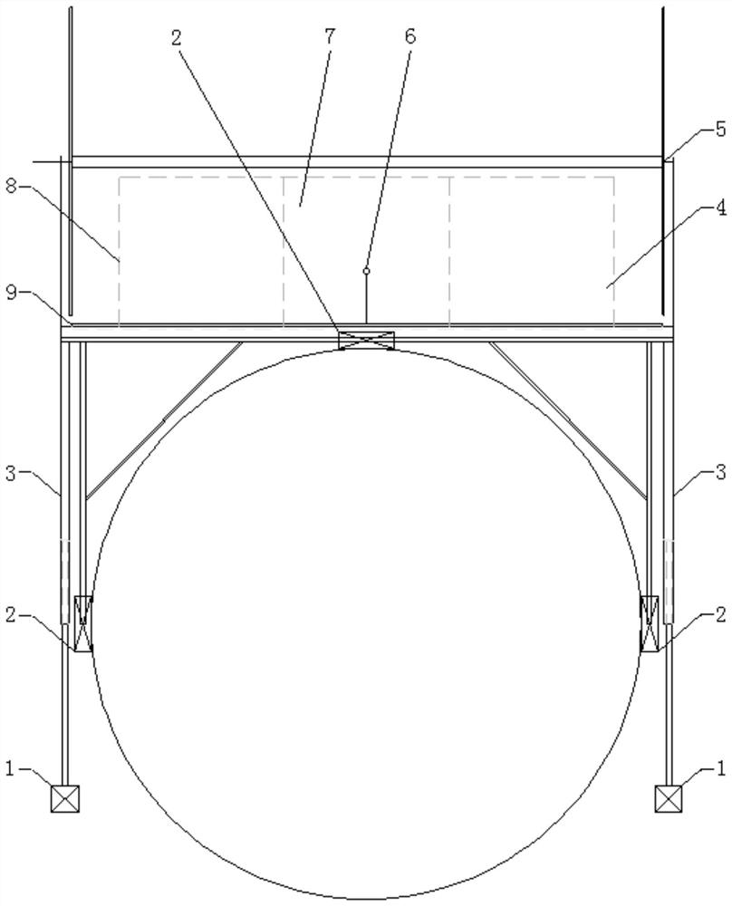
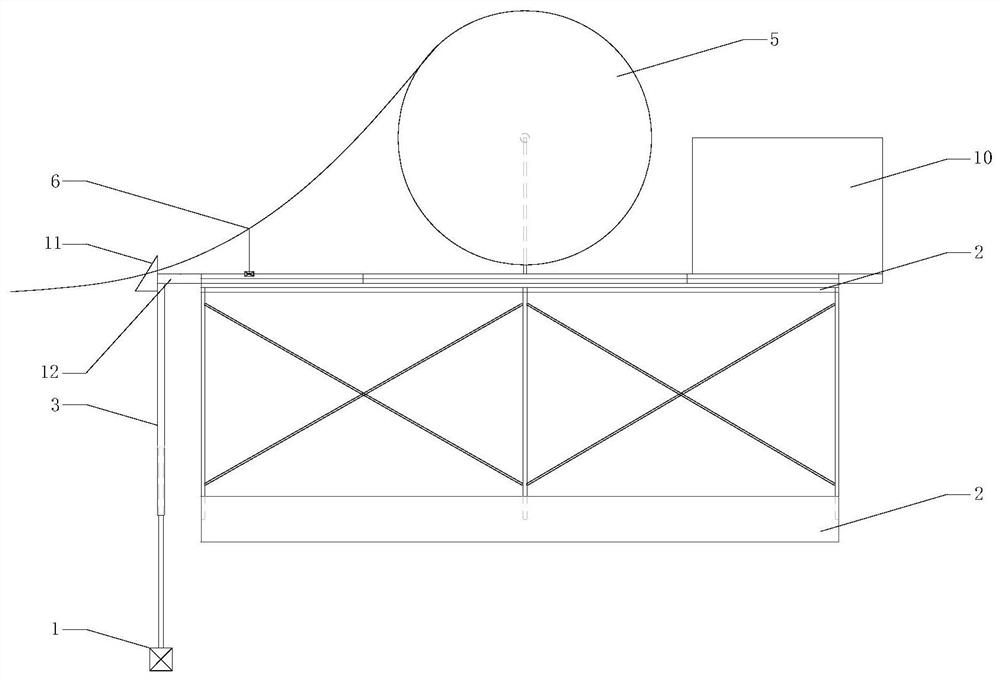
[0035] Specific implementation mode one: combine figure 1 and figure 2Describe this embodiment mode, a kind of mud contact point monitoring device in the subsea pipeline laying process of this embodiment mode, it comprises frame, traveling mechanism, monitoring mechanism, control mechanism, cable take-up mechanism and optical cable, and traveling mechanism comprises middle crawler mechanism and two The side crawler mechanism and the middle crawler mechanism are arranged on the upper part of the submarine pipeline along the length direction of the submarine pipeline. The middle crawler mechanism includes a middle support frame and a crawler transmission unit. The upper end of the frame is connected to the frame, and the two side crawler mechanisms are respectively arranged on the left and right sides of the submarine pipeline. The side crawler mechanism includes a side support frame and a crawler transmission unit. The frame is close to the side of the submarine pipeline, the...

specific Embodiment approach 2

[0038] Specific implementation mode two: combination figure 1 and figure 2 Describe this embodiment, the crawler belt drive unit of this embodiment comprises vehicle frame, drive wheel, guide wheel, crawler belt 2, magnet and crawler belt drive mechanism, drive wheel and guide wheel are respectively installed on the two ends of vehicle frame, and crawler belt 2 surrounds drive wheel Form crawler belt 2 transmission with the circumferential surface of guide wheel, magnet is installed on crawler belt 2, crawler belt driving mechanism is installed on the vehicle frame, and crawler belt driving mechanism is connected with driving wheel, realizes the rotation of driving wheel under the driving of crawler belt driving mechanism. With such arrangement, three crawlers 2 can be used to hold the submarine pipeline tightly, and each crawler is driven by an independent motor, so that the entire monitoring device can crawl along the submarine pipeline smoothly and flexibly. Magnets are a...

specific Embodiment approach 3

[0039] Specific implementation mode three: combination figure 1 and figure 2 Describe this embodiment, the crawler belt driving mechanism of this embodiment comprises motor, driving gear and driven gear, and motor is installed on the vehicle frame, and driving gear is installed on the output shaft of motor, and driven gear is installed on the axle of driving wheel, The driving gear meshes with the driven gear. So arranged, the motor output shaft rotates to drive the driving gear to rotate, the driving gear drives the driven gear to rotate, the driven gear drives the driving wheel of the crawler belt transmission unit to rotate, and the driving wheel drives the crawler belt 2 and the guide wheel to rotate. Other compositions and connections are the same as those in Embodiment 1 or Embodiment 2.


PUM


Abstract

The invention discloses a mud contact point monitoring device in a submarine pipeline laying process and a monitoring method, and relates to the field of submarine pipeline laying. The mud contact point monitoring device in the submarine pipeline laying process and the monitoring method solve the problem that an existing underwater cableless monitoring device for submarine pipeline laying is low in information transmission efficiency is solved, and solve the problem that a cable of an underwater cabled monitoring device is prone to be damaged in a complex sea area. According to the mud contact point monitoring device, a crawler belt transmission unit of a middle crawler belt mechanism is arranged at the lower end of a middle supporting frame, the upper end of the middle supporting frame is connected with a frame, crawler belt transmission units of side crawler belt mechanisms are arranged on one sides of side supporting frames, and the side supporting frames are connected with the frame; and two pan-tilts are arranged on the left side and the right side of a submarine pipeline correspondingly, the upper ends of the pan-tilts are connected with a driving module, and the driving module is arranged on the frame. The mud contact point monitoring device in the submarine pipeline laying process and the monitoring method are used for monitoring the position of a mud entering point of the submarine pipeline, and the laying position of the pipeline is adjusted in time through video information fed back by the monitoring device, so that it is guaranteed that the submarine pipeline is laid on a preset track, and laying construction of the whole submarine pipeline is carried out smoothly.

Description

technical field [0001] The invention relates to the field of submarine pipeline laying, in particular to a monitoring device and method for monitoring mud contact points during the laying of submarine pipelines. Background technique [0002] Submarine pipeline is the main component of the development and production system of offshore oil and gas fields. It is an oil and gas transportation tool connecting oil wells and platforms, platforms and onshore storage and transportation facilities. The location of submarine pipelines determines the structural safety and use of submarine pipelines. life. [0003] Due to the complexity and diversity of the submarine terrain, there are some dangerous areas such as rugged or soft mud. In order to ensure the safety of the submarine pipeline, it is necessary to design a reasonable and safe submarine pipeline laying track in advance. If the pipeline deviates from the preset laying track, it will affect the structural safety of the submarine...

Claims


Application Information

Patent Timeline
Patent Type & Authority Applications(China)
IPC IPC(8): F16L1/16F16L1/20F16M11/04F16M11/18F16M11/42B63B35/03B62D55/00
CPCF16L1/16F16L1/20F16M11/04F16M11/043F16M11/046F16M11/18F16M11/425B63B35/03B62D55/00
Inventor 李岳明尹长一曹建张国成李晔
Owner HARBIN ENG UNIV
Learn More