
Reconfigurable integrated microwave photonic band-pass filter

A band-pass filter, microwave photonic technology, applied in instruments, optics, light guides, etc., can solve problems such as difficulty in adapting to filtering performance requirements, large volume of discrete devices, bandwidth tuning limitations, etc., to improve bandwidth reconstruction range and improve suppression. ratio, the effect of reducing the bandwidth

Active Publication Date: 2021-11-23
HUAZHONG UNIV OF SCI & TECH
View PDF14 Cites 0 Cited by
  • Summary
  • Abstract
  • Description
  • Claims
  • Application Information

AI Technical Summary

Problems solved by technology

[0003] At present, the development of microwave photonic filters based on discrete devices has been relatively mature, but discrete devices have the disadvantages of large volume, high power consumption, and low stability, and have obvious limitations in practicality, so the current main research direction is Microwave Photonic Filters Based on Integrated Devices
In the prior art, some microwave photonic filters based on integrated devices have the problems of jitter in the filtering area and high insertion loss; in order to solve the problem of flat passband in the microwave photonic filters based on integrated devices, usually the micro The coupling coefficient of the ring is symmetrically designed, but this symmetrical design usually has a great limiting effect on bandwidth tuning
In the prior art, microwave photonic filters based on integrated devices are still deficient in narrow bandwidth, high rejection ratio and high flexibility, and it is difficult to adapt to different filtering performance requirements in various application paths

Method used


Image

  • Reconfigurable integrated microwave photonic band-pass filter
  • Reconfigurable integrated microwave photonic band-pass filter
  • Reconfigurable integrated microwave photonic band-pass filter

Examples


Embodiment Construction

[0044] In order to make the object, technical solution and advantages of the present invention clearer, the present invention will be further described in detail below in conjunction with the accompanying drawings and embodiments. It should be understood that the specific embodiments described here are only used to explain the present invention, not to limit the present invention. In addition, the technical features involved in the various embodiments of the present invention described below can be combined with each other as long as they do not constitute a conflict with each other.

[0045] In the description of the embodiments of the present invention, it should be noted that the azimuth relationship indicated by the terms "upper", "lower" and so on is based on the azimuth relationship shown in the drawings, or the azimuth relationship that is usually placed when the product of the invention is used , is only for the convenience of describing the present invention and simpl...


PUM


Abstract

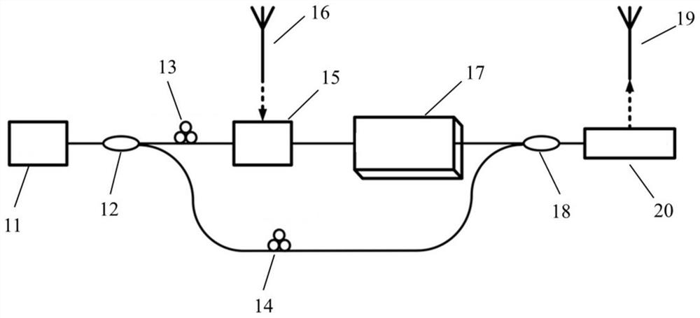
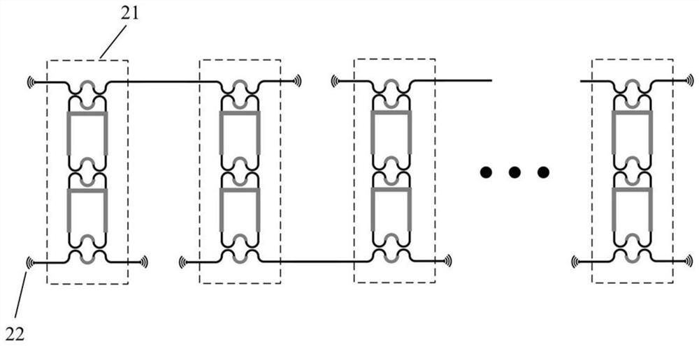
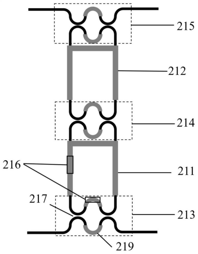
The invention discloses a reconfigurable integrated microwave photon band-pass filter, and belongs to the field of microwave photon signal processing. The reconfigurable integrated microwave photon band-pass filter comprises a semiconductor laser for outputting a continuous optical carrier signal; an optical beam splitter is used for splitting the continuous optical carrier signal into two paths of light beams; a microwave optical signal generation module is used for generating a microwave modulation signal and modulating the microwave modulation signal and one path of light beam output by the optical beam splitter to generate a microwave optical signal; a multi-stage cascaded second-order micro-ring filter is integrated, and bandwidth reconstruction and rejection ratio and center frequency tuning are carried out on the generated microwave optical signal; an optical coupler is used for combining the microwave optical signal with the other path of light beam output by the optical beam splitter; a microwave electric signal receiving module is used for converting the combined microwave optical signal into an electric signal and receiving the microwave electric signal. According to the invention, narrow-band filtering can be realized on the basis of a high radio frequency out-of-band rejection ratio, and bandwidth reconstruction of a microwave optical signal in a wide range and flexible tuning of a center frequency are realized.

Description

technical field [0001] The invention belongs to the field of microwave photon signal processing, and more specifically relates to a reconfigurable integrated microwave photon bandpass filter. Background technique [0002] Microwave photonic filters refer to devices that use optical methods and optical components to achieve filtering functions in the microwave frequency band. The biggest difference between microwave photonic filters and traditional microwave filters is that microwave photonic filters process signals in the optical domain. The advantage of this is that optical components have a huge bandwidth advantage and can directly filter high-frequency signals. The filter has good tunability and reconfigurability, and the center wavelength and filtering effect of the filter can be adjusted according to actual needs, and the microwave signal processing in the optical domain also has the characteristics of low loss and anti-electromagnetic interference, so the microwave pho...

Claims


Application Information

Patent Timeline
IPC IPC(8): H04B10/2507G02B6/293
CPCH04B10/25073G02B6/29343
Inventor 于源刘一凡张新亮
Owner HUAZHONG UNIV OF SCI & TECH
Learn More