Eureka AIR delivers breakthrough ideas for toughest innovation challenges, trusted by R&D personnel around the world.

Round pin-point gate pouring molding structure

A fine nozzle and circular technology, which is applied in the field of circular fine nozzle pouring mold structure, can solve the problems of asymmetrical gate arrangement, discontinuous flow of molten material, blockage of air passage, etc., to avoid excessive mold temperature difference Larger, speed up the molding rate, and ensure the effect of connection strength

Inactive Publication Date: 2021-11-23
深圳市华中思明通科技有限公司
View PDF0 Cites 2 Cited by
  • Summary
  • Abstract
  • Description
  • Claims
  • Application Information

AI Technical Summary

Problems solved by technology

[0004] The object of the present invention is to provide a kind of circular fine nozzle pouring mold structure, to solve the circular fine nozzle pouring mold structure technology on the market proposed in the above background technology, mainly rely on molten materials for pouring, so that injection molded products are formed , use the mold clamping between the templates to make the mold cavity for product production, but in the injection mold, the interference of the gas during the filling process often causes silver streaks or tiny bubbles to appear on the surface of the product or bubbles are formed in the thick wall of the product, and the gate Poor location, too small gate, asymmetric gate arrangement of multi-gate parts, small runners, and even unreasonable mold cooling system will cause too large difference in mold temperature and cause the molten material to flow poorly in the mold cavity. Continuous, blocking the passage of the air, even when the temperature of the mold itself is too low, water droplets will remain in the cavity. When the high-temperature material enters the cavity, it will react, resulting in the generation of water vapor, which will cause the product to produce Bubbles, a problem that affects the quality of injection molded products

Method used


Image

  • Round pin-point gate pouring molding structure
  • Round pin-point gate pouring molding structure
  • Round pin-point gate pouring molding structure

Examples


Embodiment Construction

[0055] In the description of the present invention, unless otherwise stated, the meaning of "plurality" is two or more; the terms "upper", "lower", "left", "right", "inner", "outer" , "front end", "rear end", "head", "tail", etc. indicate the orientation or positional relationship based on the orientation or positional relationship shown in the drawings, and are only for the convenience of describing the present invention and simplifying the description, rather than Nothing indicating or implying that a referenced device or element must have a particular orientation, be constructed, and operate in a particular orientation should therefore not be construed as limiting the invention. In addition, the terms "first", "second", "third", etc. are used for descriptive purposes only and should not be construed as indicating or implying relative importance.

[0056] In the description of the present invention, it should be noted that unless otherwise specified and limited, the terms "c...


PUM


Abstract

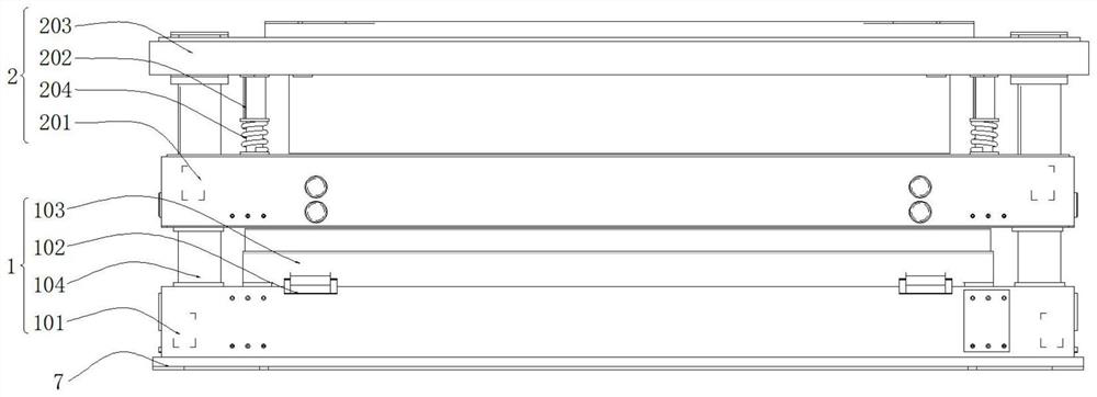
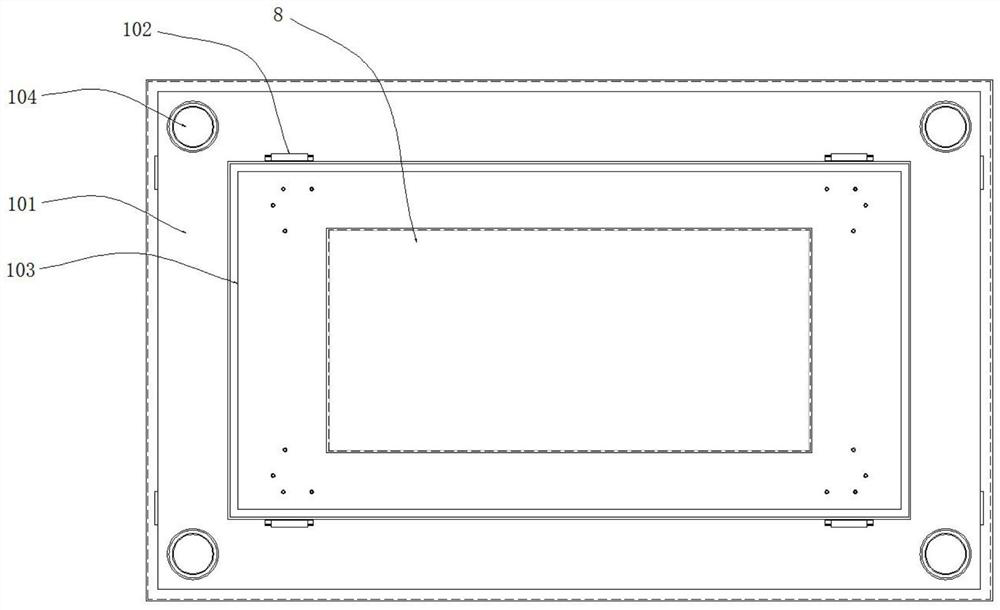
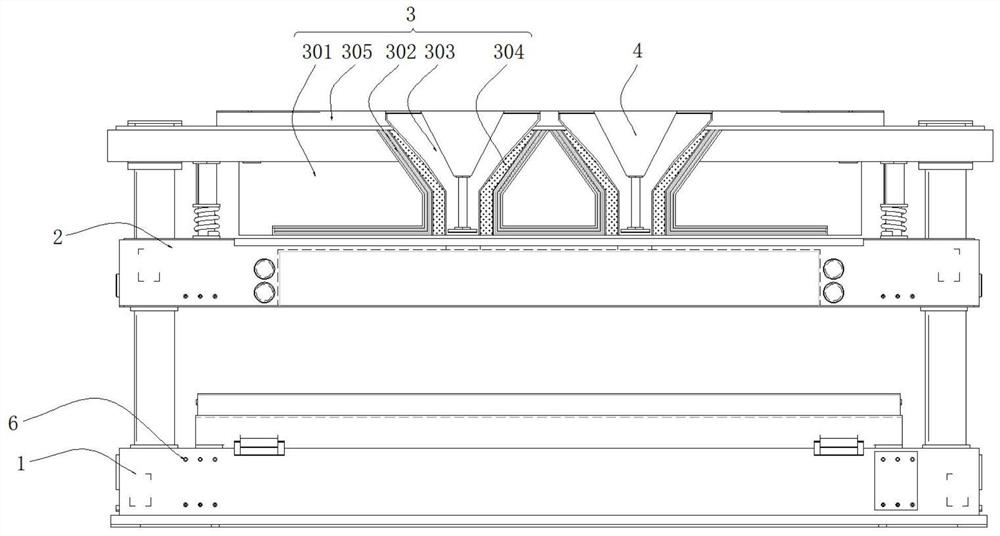
The invention discloses a round pin-point gate pouring molding structure. The structure comprises a supporting mechanism, a mold closing mechanism is arranged at the top of the upper end of the supporting mechanism, a base plate is arranged at the bottom of the lower end of the supporting mechanism, screws are arranged on the periphery of the outer side of the supporting mechanism, and a lower mold cavity is formed in the top of the upper end of the supporting mechanism. A molding mechanism is arranged on the inner side of the upper end of the mold closing mechanism. Auxiliary feeding mechanisms are arranged on the two sides of the interior of the molding mechanism. According to the structure, a heating wire layer is used for heating the upper mold cavity, so that the situation that the temperature in the mold cavity is too low, water vapor is generated due to direct contact with melt, even the water vapor is accumulated in the mold cavity, flowing and molding pressure of the melt are affected, and bubbles are generated in a product is avoided. Through the heating of the heating wire layer, preheating operation can be carried out before molding, so that the situation that melt flows discontinuously in the mold cavity due to too large mold temperature difference is avoided.

Description

technical field [0001] The invention relates to the technical field of injection moulds, in particular to a circular thin nozzle inlet casting mold structure. Background technique [0002] Today, the sprue is the last hurdle for molten plastic to enter the mold cavity through the gating system. It is the feed channel connecting the runner and the cavity, and it is also the shortest part. Its function makes the molten plastic accelerate when it enters the cavity, which is conducive to The cavity is filled quickly, and the plastic at the gate condenses first after molding to seal the cavity, prevent the molten plastic from flowing backwards, and prevent the pressure of the cavity from dropping too fast, resulting in shrinkage cavities or depressions on the product. Separation to shape the product. [0003] The structure technology of the circular fine nozzle pouring mold on the market mainly relies on pouring of molten materials to form the injection molded product, and uses ...

Claims


Application Information

Patent Timeline
Patent Type & Authority Applications(China)
IPC IPC(8): B29C45/26B29C45/73B29C45/67B29C45/27B29C45/77
Inventor 王鸿鸣沈炳龙罗治永林海光潘成扬
Owner 深圳市华中思明通科技有限公司
Why Eureka
Eureka Blog
Learn More