
Real-time fluorescence imaging intelligent enhancement method and device

A fluorescent imaging and intelligent technology, applied in image enhancement, image analysis, image data processing, etc., can solve the problems of cells unable to bear high concentration of fluorescent labels, limit influence of photon noise, low signal-to-noise ratio, etc., and achieve biological structure and Clearly visible effects on life processes

Pending Publication Date: 2021-11-19
TSINGHUA UNIV
View PDF0 Cites 2 Cited by
  • Summary
  • Abstract
  • Description
  • Claims
  • Application Information

AI Technical Summary

Problems solved by technology

[0004] The problem of low signal-to-noise ratio in fluorescence microscopy imaging is mainly caused by the following aspects: (1) The photon yield of fluorescent protein is low, that is to say, only a small amount of fluorescent photons can be produced per unit fluorescent molecule, which leads to The source leads to the shortage of fluorescent photons
(2) The fluorescent protein content in cells is low, and healthy cells cannot bear high concentrations of fluorescent labels, which further reduces the intensity of fluorescent signals
(3) Since the excitation light will inevitably bring about photobleaching, phototoxicity, photodamage and other problems, it is necessary to maintain a low dose of excitation power to maintain cell health and reliable conclusions
(4) The detection of photons is uncertain. The quantum properties of light determine that any detector cannot accurately detect the number of photons. When the number of fluorescent photons is small, the photon noise limit has a significant impact
In a nutshell, the signal-to-noise ratio of fluorescence microscopy imaging is limited by biology, physics, chemistry, etc., making it difficult to improve the signal-to-noise ratio of fluorescence imaging using traditional physical, chemical, and biological methods.

Method used


Image

  • Real-time fluorescence imaging intelligent enhancement method and device
  • Real-time fluorescence imaging intelligent enhancement method and device
  • Real-time fluorescence imaging intelligent enhancement method and device

Examples


Embodiment Construction

[0040]Embodiments of the present invention are described in detail below, examples of which are shown in the drawings, wherein the same or similar reference numerals designate the same or similar elements or elements having the same or similar functions throughout. The embodiments described below by referring to the figures are exemplary and are intended to explain the present invention and should not be construed as limiting the present invention.

[0041] The real-time fluorescent imaging intelligent enhancement method and device according to the embodiments of the present invention will be described below with reference to the accompanying drawings.

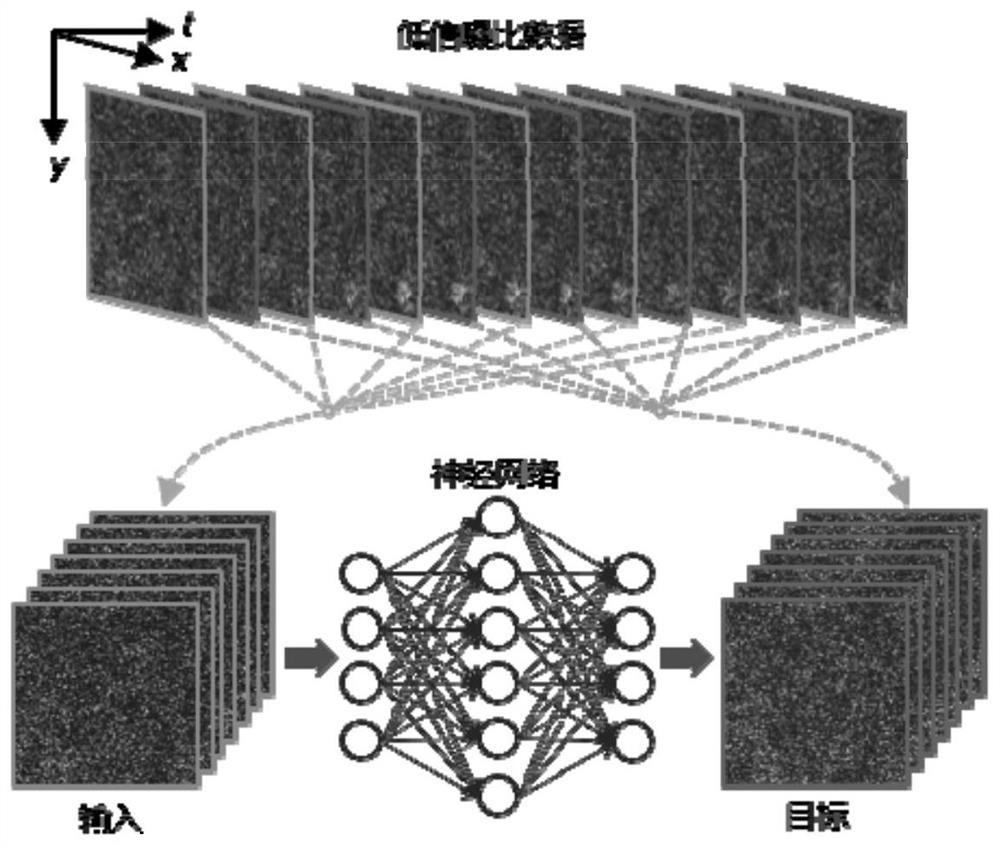
[0042] First, the principle diagram and data processing flow of the real-time fluorescence imaging intelligent enhancement method proposed according to the embodiment of the present invention will be described with reference to the accompanying drawings.

[0043] The principles and data processing flow of the embodiments of th...


PUM


Abstract

The invention discloses a real-time fluorescence imaging intelligent enhancement method and device, and the method comprises the steps: training a neural network model in advance through self-supervised learning, loading the trained neural network model to an arithmetic unit, and enabling the loading process to comprise the optimization of the neural network model; converting the image through an imaging system interface to obtain a continuous data stream, inputting the continuous data stream into an arithmetic unit, processing the continuous data stream through a neural network model trained on the arithmetic unit, and outputting the processed data in the form of the continuous data stream, wherein the data processing time sequence is processed, so that real-time data processing and synchronous display are realized. According to the method, image enhancement can be carried out in real time while the fluorescence microscope is used for shooting, so that the signal-to-noise ratio of data is improved.

Description

technical field [0001] The invention relates to the technical fields of optical microscopic imaging and intelligent image processing, and in particular to a real-time fluorescence imaging intelligent enhancement method. Background technique [0002] Fluorescence microscopy is a core research method in life sciences. Fluorescence microscopy imaging includes fluorescent labeling and optical imaging. It is necessary to first use fluorescent proteins or organic fuels to specifically mark the structure or substance to be observed, and then use a fluorescence microscope for observation. Fluorescence microscopy first emits short-wavelength light to excite fluorescent molecules, and the fluorescent molecules are stimulated to emit long-wavelength fluorescent photons. The fluorescent photons are received by the detector to form an image, thereby reflecting the specific structure and material distribution. Because fluorescence imaging can specifically mark the specified structure and...

Claims


Application Information

Patent Timeline
Patent Type & Authority Applications(China)
IPC IPC(8): G06T5/00G06N3/04
CPCG06T2207/10064G06N3/045G06T5/70
Inventor 乔晖王好谦戴琼海李欣阳
Owner TSINGHUA UNIV
Learn More