


Quick Research
Generate reliable direction feasibility study reports for your R&D in just a few steps.

Technical Q&A
Discover and master advanced knowledge NOW. Basics, ideas, possibilities, all at once.

Find Solutions
As an expert in R&D theories, this can generate solutions to your technical problems instantly.

Evaluate Feasibility
Analyze your overall solution with one click, know your potential R&D risks in advance.

Monitor Landscape
Get weekly tech updates, stay abreast of the latest tech innovations and key insights.
Modular distributed air source heat pump unit
An air source heat pump, distributed technology, applied in the field of heat pumps, can solve the problems of inability to guarantee the hydraulic balance of the internal and terminal systems of the unit, difficult construction and site selection, and large floor space, so as to facilitate the design and site selection, and facilitate the overall equipment. The effect of installation and space saving
- Summary
- Abstract
- Description
- Claims
- Application Information
AI Technical Summary
Problems solved by technology
Method used
Image

Examples
Embodiment 1
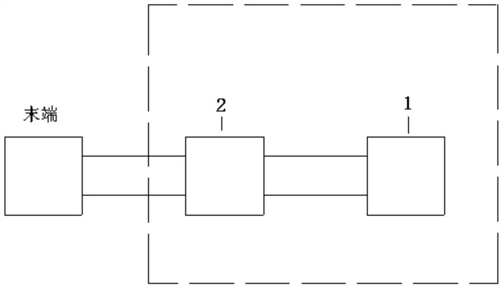
[0031] like Figure 1-6 As shown, the present invention is a modular distributed air source heat pump unit, which includes a heat pump circulation module 1 and an end circulation module 2. The heat pump circulation module 1 and the end circulation module 2 are connected by a closed insulation pipe, and the heat pump cycle Module 1 is responsible for extracting the heat and cold in the atmosphere, and the terminal circulation module 2 is responsible for sending the heat and cold to the end of the user.
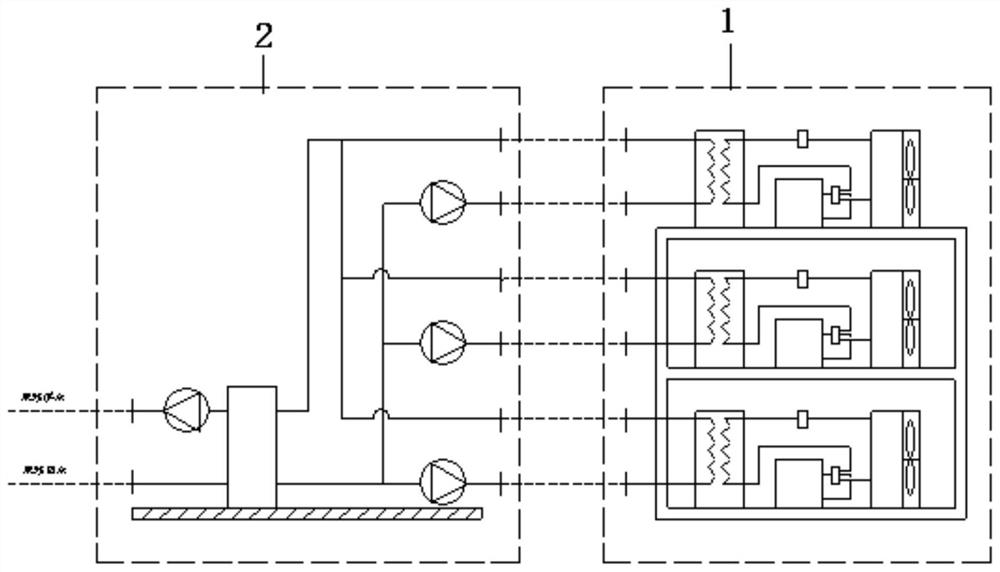
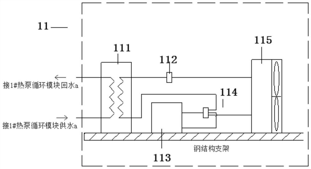
[0032] Among them, the heat pump cycle module 1 adopts a modular design and is assembled by two or more standardized heat pump cycle modules 11, and the refrigerant side of the heat pump cycle modules 11 are independent from each other, and the water side is connected in parallel. The heat pump cycle The module 11 is composed of energy side heat exchanger 111, expansion valve 112, compressor 113, four-way valve 114 and air side heat exchanger 115, energy side heat exchanger 111...
Embodiment 2
[0036] Wherein, the terminal circulation module 2 is a distributed circulating water supply mode, and is equipped with a terminal circulation pump 21, a module pump 22, an equalizing tank 23, and the terminal circulating pump 21 forms a terminal water circulation with the equalizing tank 23. The pressure tank 23 forms a heat pump water cycle, and the terminal circulation pump 21, the module pump 22, and the pressure equalization tank 23 adopt a secondary pump system and are connected through the same pipeline.
[0037] Terminal circulation pump 21, module pump 22, pressure equalization tank 23, the cycle sequence of terminal circulation pump 21 is heat pump circulation module 11 return water port → module pump 22 → equal pressure tank 23 → terminal circulation pump 21 water supply port, terminal circulation pump 21 return water port →Equalizing tank 23→Water supply port of heat pump circulation module 11→Water supply port of heat pump circulation module 11.
[0038] A specific...
PUM
 Abstract
Description
Claims
Application Information
 - R&D Engineer
- R&D Manager
- IP Professional
- Industry Leading Data Capabilities
- Powerful AI technology
- Patent DNA Extraction
Browse by: Latest US Patents, China's latest patents, Technical Efficacy Thesaurus, Application Domain, Technology Topic, Popular Technical Reports.
© 2024 PatSnap. All rights reserved.Legal|Privacy policy|Modern Slavery Act Transparency Statement|Sitemap|About US| Contact US: help@patsnap.com