
Signal transmission structure and circuit structure

A technology of signal transmission and circuit structure, applied in the direction of printed circuit, printed circuit parts, electrical components, etc., can solve the problems of large circuit board area and high production cost, and achieve the effect of avoiding sudden change of impedance, reducing production cost and reducing occupation

Pending Publication Date: 2021-11-16
SPREADTRUM COMM (SHANGHAI) CO LTD
View PDF3 Cites 0 Cited by
  • Summary
  • Abstract
  • Description
  • Claims
  • Application Information

AI Technical Summary

Problems solved by technology

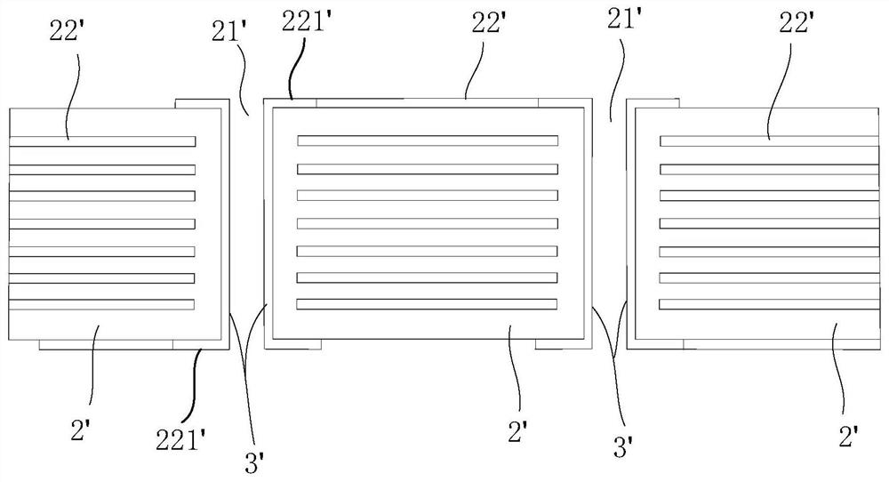
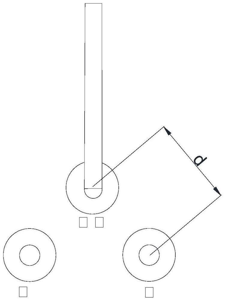
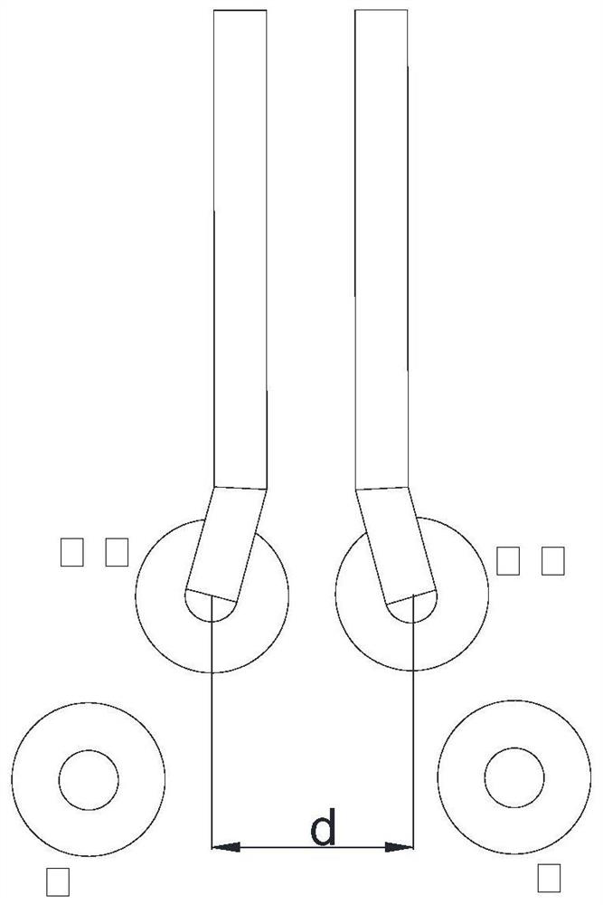
[0004] When the electrical signal is transmitted in the circuit board, the flow direction of the signal is from the driver, along the wiring on the circuit board, to the load; then from the load end along the ground plane, back to the drive end through the shortest path or the path with the least impedance , for high-speed signals, the shortest path (minimum impedance) is often the reference ground directly below the transmission line. Therefore, in order to allow the return path to return to the bottom of the signal as soon as possible, the existing technology usually adds a ground hole near the signal layer change. The addition of ground holes makes it take up a larger area of ​​the circuit board, and the production cost is high

Method used


Image

  • Signal transmission structure and circuit structure
  • Signal transmission structure and circuit structure
  • Signal transmission structure and circuit structure

Examples


Embodiment Construction

[0028] In order to make the purpose, technical solution and advantages of the present application clearer, the present application will be further described in detail below in conjunction with the accompanying drawings and embodiments. It should be understood that the specific embodiments described here are only used to explain the present application, and are not intended to limit the present application.

[0029] In the description of this application, unless otherwise clearly specified and limited, the terms "first" and "second" are only used for the purpose of description, and cannot be understood as indicating or implying relative importance; unless otherwise specified or stated , the term "plurality" refers to two or more; the terms "connection", "fixation" and so on should be understood in a broad sense, for example, "connection" can be a fixed connection, a detachable connection, or an integrated Connected, or electrically connected; either directly or indirectly throu...


PUM


Abstract

The invention discloses a signal transmission structure and a circuit structure. The signal transmission structure is used for transmitting a high-speed signal in a circuit; the signal transmission structure comprises a signal transmission part, an insulation part and a signal backflow part, the signal transmission part is used for transmitting a driving signal, the insulation part coats the outer surface of the signal transmission part, and the signal backflow part is arranged on the outer surface of the insulation part and used for transmitting backflow signals; and the signal transmission direction of the signal backflow part and the signal transmission direction of the signal transmission part are parallel and opposite to each other. When the high-speed signal is transmitted, the driving signal can circulate between two circuit layers through the signal transmission part, the backflow signal can flow back to the position below the signal as soon as possible through the signal backflow part, the problem of impedance abrupt change caused by high-speed signal layer change transmission is avoided; and ground holes do not need to be formed, the occupied area of a substrate is reduced, and the production cost is reduced.

Description

technical field [0001] The present application relates to the technical field of high-speed signal transmission in circuits, in particular to a signal transmission structure for transmitting high-speed signals in circuits and a circuit structure with the signal transmission structure. Background technique [0002] After the production of the chip (integrated circuit) is completed, the corresponding pins need to be led out to the printed circuit board, and connected to other chips, interfaces or passive devices through the printed circuit board to make modules, systems or products, so as to facilitate be utilized. [0003] As the functions of modules, systems or products become more and more powerful, the structure of the circuit board (chip substrate or printed circuit board) becomes more and more complex. Along the thickness direction of the circuit board, there are usually multiple circuit layers in the circuit board. , in order to realize the electrical connection betwee...

Claims


Application Information

Patent Timeline
IPC IPC(8): H05K1/11H05K1/16
CPCH05K1/16H05K1/115
Inventor 雷江
Owner SPREADTRUM COMM (SHANGHAI) CO LTD
Learn More