
A kind of coaxial connector and connector assembly

A technology of coaxial connectors and connectors, which is applied to the parts, connections, and contact parts of the connecting device, can solve problems such as overvoltage, plastic deformation, and affecting the overall performance of the connector module, so as to avoid sudden changes in diameter, Low cost, good for high-frequency signal transmission

Active Publication Date: 2021-03-23
CHINA AVIATION OPTICAL-ELECTRICAL TECH CO LTD
View PDF11 Cites 0 Cited by
  • Summary
  • Abstract
  • Description
  • Claims
  • Application Information

AI Technical Summary

Problems solved by technology

[0008] The purpose of the present invention is to provide a coaxial connector to solve the technical problem in the prior art that the external contact elastic member on the connector is prone to overpressure and cause plastic deformation; at the same time, the present invention also provides a coaxial connector using the above The connector assembly of the coaxial connector is used to solve the technical problem in the prior art that the external contact elastic member on a single connector is prone to overpressure and produces plastic deformation, which in turn affects the overall performance of the connector module

Method used


Image

  • A kind of coaxial connector and connector assembly
  • A kind of coaxial connector and connector assembly
  • A kind of coaxial connector and connector assembly

Examples


specific Embodiment 1

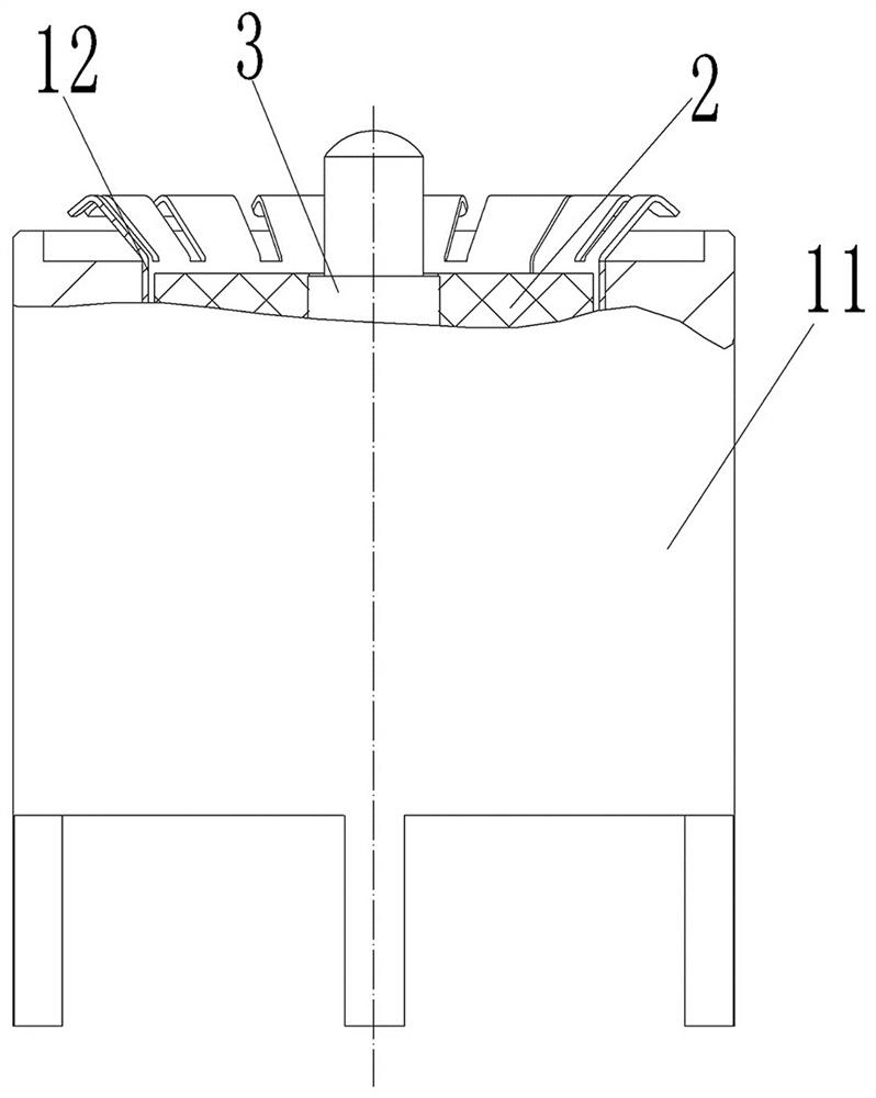
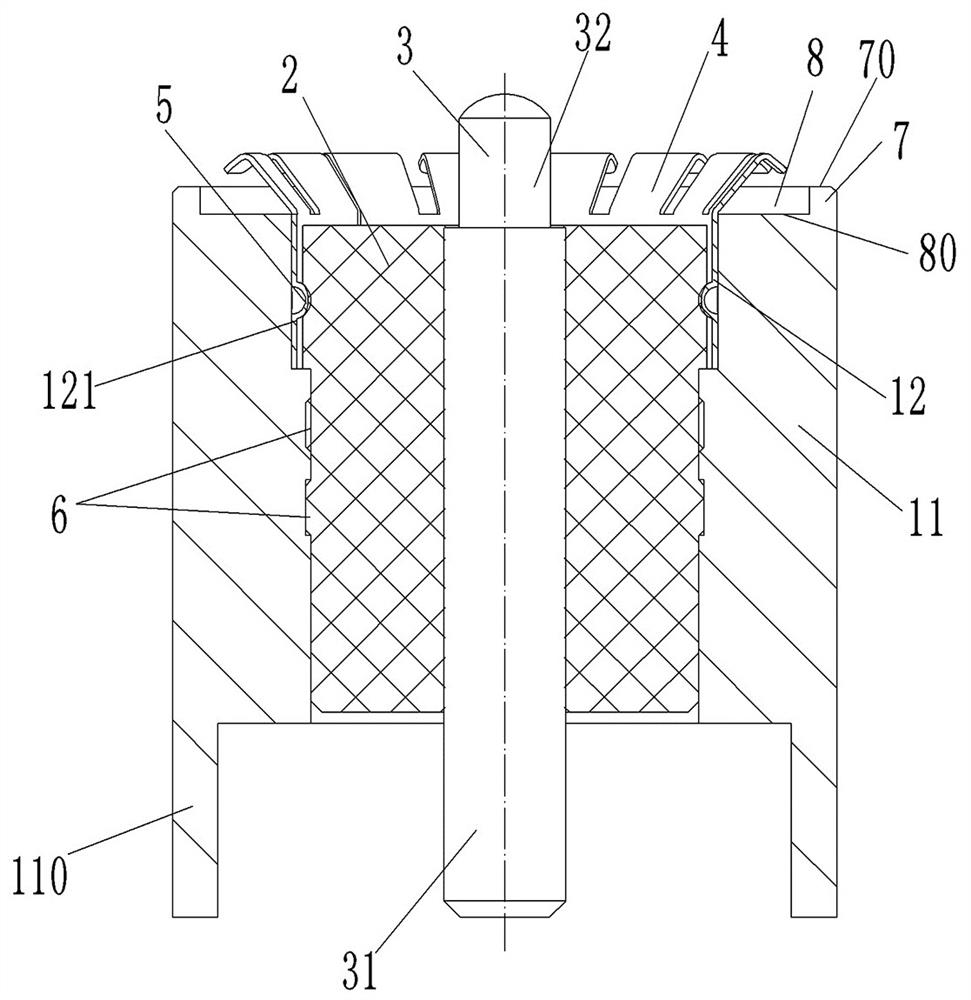
[0072] Such as Figure 2 to Figure 5 As shown, in this embodiment, the coaxial connector includes an outer shell 11 , an inner insulator 2 , a central conductor 3 and an outer contact conductor portion 12 . Specifically, the central conductor 3 is fixed in the inner insulator 2, the outer shell 11 is a conductor, the inner insulator 2 is tightly fitted and fixedly inserted in the outer shell 11, and the outer contact conductor part 12 is inserted in the inner insulator 2 and the outer shell 11. Between, so that the outer contact conductor part 12 and the outer shell 11 are conductively fixed together, and then realize the separate conductive connection of the outer shell 11 and the outer contact conductor part 12 .

[0073] Such as image 3 As shown, the rear end of the center conductor 3 is a center conductor fixed part 31, and the front end is a center conductor floating part 32. The center conductor fixed part 31 is used to be fixedly connected to a corresponding connector...

specific Embodiment 2

[0097] Such as Figure 6 As shown, compared with the coaxial connector structure in Embodiment 1, the main difference lies in that the outer contact shrapnel of the outer contact conductor part in Embodiment 1 are all folded outwards, while the outer contact shrapnel of the outer contact conductor part 400 in Embodiment 2 The contact springs 401 are all folded inwards. At this time, it should be noted that the outer contact springs can be designed to be tapered to avoid accidental interference when they are folded.

[0098] In this embodiment, all the inwardly folded outer contact shrapnels are obliquely folded so as to form a trumpet-like structure with gradually changing diameters as a whole, so as to obtain better gradually changing impedance. In other embodiments, the inverted outer contact elastic piece can also be in the shape of a broken line, forming a sudden change, as long as it has sufficient elastic pressing force.

[0099] During installation, the outer contact c...

specific Embodiment 3

[0103] Such as Figure 7 As shown, compared with the coaxial connector structure in Embodiment 1, the main difference is that the front end stop surface in Embodiment 1 is set at the front end of the outer shell, while the front end stop surface 104 in this embodiment is set at The front end of the internal insulator 103 can also be matched with the movable PCB board as the target connector to limit the corresponding crimping range.

[0104] Same as Embodiment 1, in this embodiment, the outer contact shrapnel of the outer contact conductor part 105 is also folded outwards, and an outer rear positioning surface 102 is provided at the front end of the outer shell 101 to stop with the front end on the above-mentioned inner insulator 103. The surface 104 is misplaced to form an avoidance space to ensure the normal deformation of the external contact shrapnel after being compressed.


PUM


Abstract

The invention relates to a coaxial connector and a connector assembly. The coaxial connector comprises an internal insulator, an elastic floating center conductor, an outer contact conductor part andan outer shell, wherein the outer shell and the outer contact conductor part are electrically connected and assembled or insulated; a front end stop surface arranged at the front end of the internal insulator and / or the outer shell body for stop-fitting with the target connector to limit the crimping amplitude; and an avoidance space arranged beside the outer contact elastic member and is used foraccommodating the outer contact elastic member deformed by the top pressure of the target connector. The front end stop surface is arranged at the front end of the internal insulator and / or the outershell body during assembly to stop-fit with the target connector, thus limiting the crimping amplitude. The deformed outer contact elastic piece can be accommodated by using the avoidance space during crimping to effectively cooperate with the front end stop surface, avoid the problem of over-pressure and further effectively protect the outer contact elastic member.

Description

technical field [0001] The invention belongs to the technical field of coaxial connectors, and in particular relates to a coaxial connector and a connector assembly. Background technique [0002] Conventionally, when transmitting radio frequency signals between two circuit boards, a traditional SMP three-piece structure is usually adopted, that is, two sockets 200 are respectively soldered to the two circuit boards 100 to be connected, and an adapter 300 is used in the middle to realize a floating connection. This structure has been widely used in the field of communication, but with the increasingly higher requirements for equipment miniaturization, easy maintenance and low cost, this connection method cannot meet the use requirements due to its large size and troublesome installation and operation. [0003] At present, there are also connector modules used to realize board-to-board connection, such as the connector module disclosed in the Chinese utility model patent whose...

Claims


Application Information

Patent Timeline
Patent Type & Authority Patents(China)
IPC IPC(8): H01R24/38H01R13/502H01R13/629H01R13/15
CPCH01R13/15H01R13/502H01R13/629H01R24/38
Inventor 梅晓云吉园园崔艳磊张志中
Owner CHINA AVIATION OPTICAL-ELECTRICAL TECH CO LTD
Learn More