


Quick Research
Generate reliable direction feasibility study reports for your R&D in just a few steps.

Technical Q&A
Discover and master advanced knowledge NOW. Basics, ideas, possibilities, all at once.

Find Solutions
As an expert in R&D theories, this can generate solutions to your technical problems instantly.

Evaluate Feasibility
Analyze your overall solution with one click, know your potential R&D risks in advance.

Monitor Landscape
Get weekly tech updates, stay abreast of the latest tech innovations and key insights.
Peeling device for assembling connecting wire of electrical equipment
A technology for electrical equipment and connecting wires, applied in the field of stripping devices for connecting wire assembly, can solve problems such as affecting the use of connecting wires, easily damaging the core of the connecting wire, and insufficiently uniform strength, so as to improve the peeling efficiency and the cutting efficiency. Effect
- Summary
- Abstract
- Description
- Claims
- Application Information
AI Technical Summary
Problems solved by technology
Method used
Image

Examples
Embodiment 1
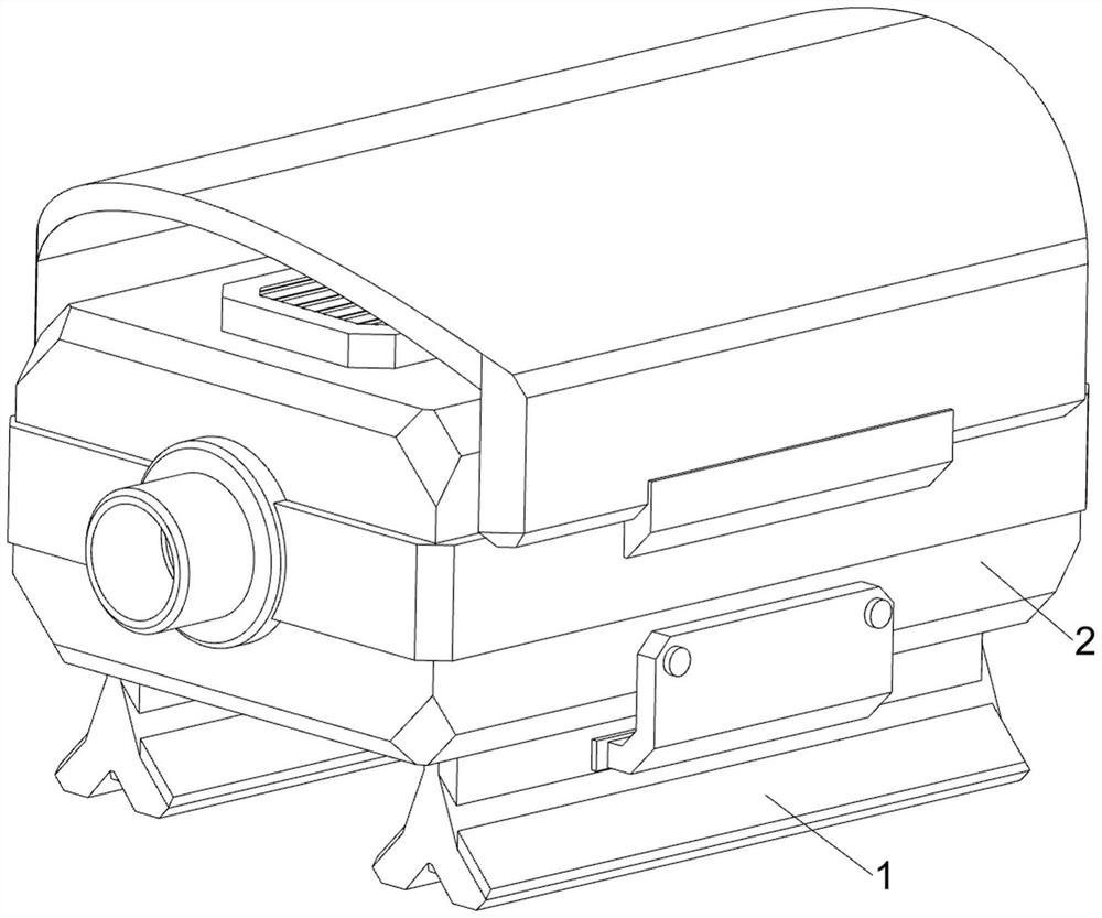
[0037] A stripping device for connecting wire assembly of electrical equipment, such as Figure 1-Figure 7 As shown, it includes a first support 1, a casing 2, a cutting knife 3, a cutting assembly 4 and a pressing assembly 5. The bottom of the casing 2 is provided with a first support 1 on both sides, and the right side of the casing 2 is provided with a cutting assembly 4. A cutting knife 3 is symmetrically connected to the cutting assembly 4 , and a pressing assembly 5 is arranged inside the housing 2 , and the pressing assembly 5 cooperates with the cutting assembly 4 .
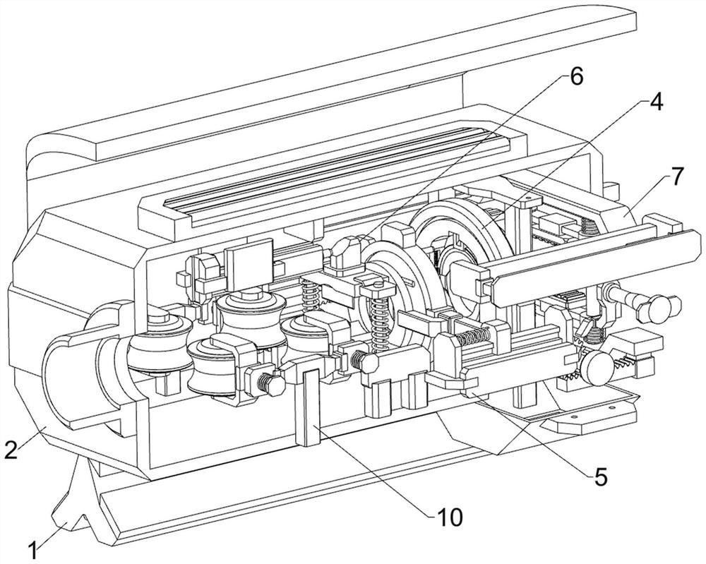
[0038]The cutting assembly 4 includes a first support frame 401, a first turntable 402, a first slider 403, a first spring 404 and a first contact block 405. The right side of the housing 2 is provided with a first support frame 401, and the first support frame 401 The inside rotation type is provided with a first turntable 402, and the front and rear sides of the first turntable 402 are symmetrically sli...
Embodiment 2
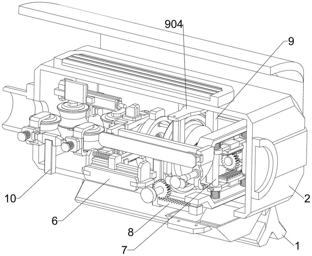
[0042] On the basis of Example 1, such as Figure 8-Figure 17 As shown, a fixing assembly 6 is also included, and the fixing assembly 6 includes a third support frame 601, a fixing splint 602, a first guide rod 603, a third spring 604, a first splint 605 and a third contact block 606, inside the housing 2 A third support frame 601 is arranged on the front and rear sides of the middle, and a fixed splint 602 is arranged between the inner sides of the third support frame 601. First guide rods 603 are arranged on the front and rear sides of the top of the fixed splint 602, and between the upper sides of the first guide rods 603 The sliding type is provided with a first splint 605, and a third spring 604 is arranged symmetrically between the first splint 605 and the fixed splint 602. Three contact blocks 606 , the telescopic rod of the electric push rod 501 cooperates with the third contact block 606 .
[0043] After the connecting wire passes through the bearing 506 to the right...
PUM
 Abstract
Description
Claims
Application Information
 - R&D Engineer
- R&D Manager
- IP Professional
- Industry Leading Data Capabilities
- Powerful AI technology
- Patent DNA Extraction
Browse by: Latest US Patents, China's latest patents, Technical Efficacy Thesaurus, Application Domain, Technology Topic, Popular Technical Reports.
© 2024 PatSnap. All rights reserved.Legal|Privacy policy|Modern Slavery Act Transparency Statement|Sitemap|About US| Contact US: help@patsnap.com