
Impactor clamping ring machining clamp and method

A technology of impactor and snap ring, which is used in manufacturing tools, metal processing equipment, metal processing machinery parts, etc. The effect of improving processing efficiency

Pending Publication Date: 2021-11-12
CHANGSHA HEIJINGANG IND CO LTD
View PDF0 Cites 1 Cited by
  • Summary
  • Abstract
  • Description
  • Claims
  • Application Information

AI Technical Summary

Problems solved by technology

The snap ring is usually set as a flat-mouth ring clip. In order to be able to be transported to one end of the drill bit, there is usually a ventilation groove on the inner wall of the snap ring. The groove adopts CNC milling. This processing method requires two clamping (one turning, one milling). After the turning process is completed, it needs to be transferred to the milling machine for processing, which increases the auxiliary processing time. On the other hand, the snap ring is generally made of steel. parts, the hardness of the material is relatively high, in order to avoid chipping, the CNC milling cutter will use the processing method of small amount of cutting, small depth of cut, and low speed. The choice of milling processing method makes the processing efficiency of the snap ring low

Method used


Image

  • Impactor clamping ring machining clamp and method
  • Impactor clamping ring machining clamp and method

Examples


Embodiment Construction

[0039] In order to enable those skilled in the art to better understand the technical solutions in the present application, the technical solutions in the embodiments of the present application will be clearly and completely described below in conjunction with the drawings in the embodiments of the present application. Obviously, the described The embodiments are only some of the embodiments of the present application, but not all of them. Based on the embodiments in this application, all other embodiments obtained by persons of ordinary skill in the art without creative efforts shall fall within the scope of protection of this application.

[0040]In the description of the present invention, it should be understood that the terms "upper", "lower", etc. indicating orientation or positional relationship are only for the convenience of describing the present invention and simplifying the description, rather than indicating or implying that the referred components or elements must...


PUM


Abstract

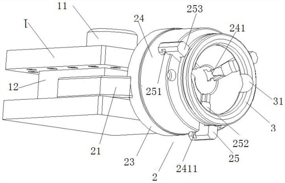
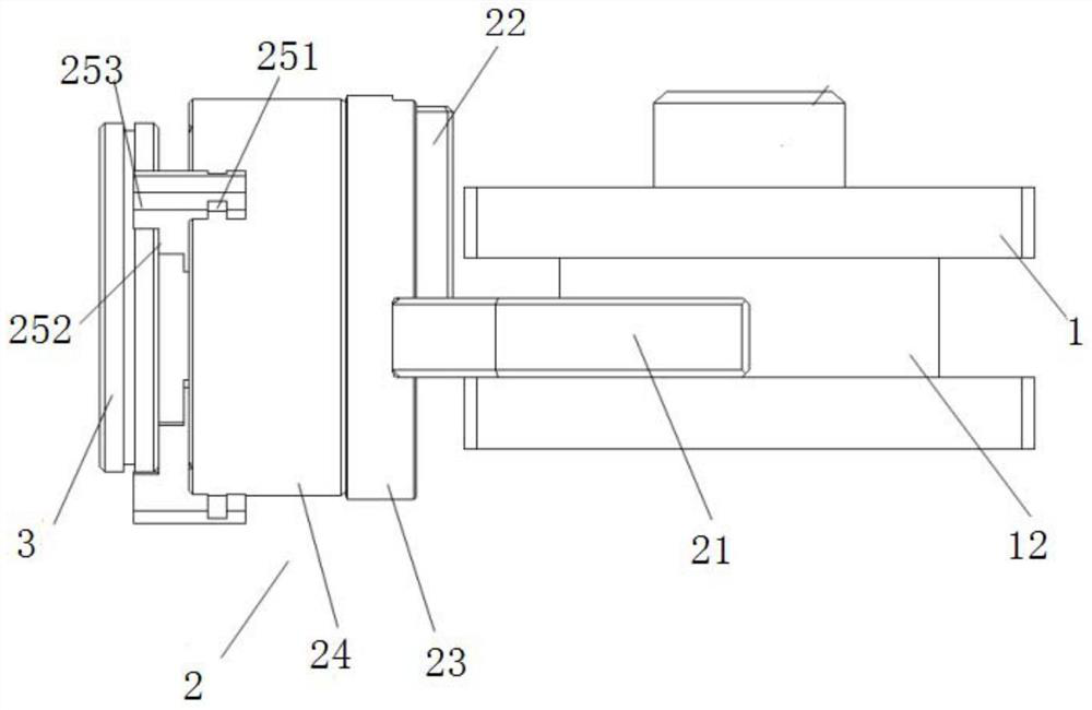
The invention relates to an impactor clamping ring machining clamp. The impactor clamping ring machining clamp comprises a frame body installed on a lathe tool rest and a clamping device detachably connected with the frame body; the clamping device is used for clamping a to-be-machined clamping ring, so that the end surface of the clamping ring can be perpendicular to the axis of a formed milling cutter installed on a lathe, and the clamping device is driven by the lathe tool rest to move in the axial direction of the clamping ring or move in the radial direction of the clamping ring. The invention further relates to an impactor clamping ring machining method. The impactor clamping ring machining clamp is adopted in the impactor clamping ring machining method. The impactor clamping ring machining clamp and the impactor clamping ring machining method are applied to the lathe, clamping ring machining can be completed on one piece of lathe equipment, a ventilation groove is machined in a numerical-control turning mode, the machining efficiency is higher than that of numerical-control milling, and then the machining efficiency of the overall clamping ring is improved.

Description

technical field [0001] The invention relates to the technical field of processing and manufacturing of impactors, in particular to a processing fixture and a processing method for a snap ring of an impactor. Background technique [0002] In recent years, as my country has continuously increased investment in infrastructure and various mines, the pneumatic down-the-hole hammer has simple structure, convenient operation, easy maintenance, effective removal of bottom cuttings, and is not affected by the drilling depth. Limitation, can reduce drilling tool wear and other advantages, has received great attention in the field of rock crushing machinery technology. With the rapid development of pneumatic down-the-hole hammer drilling technology, its application fields have been continuously expanded, from the initial blast hole construction, to hydrological water well drilling, geological core exploration, reservoir dam foundation curtain grouting, engineering geological exploration...

Claims


Application Information

Patent Timeline
Patent Type & Authority Applications(China)
IPC IPC(8): B23B5/00B23B25/06B23B31/02B23Q1/00B23B21/00
CPCB23B5/00B23B25/06B23B31/02B23Q1/00
Inventor 杨日平陈真杨湘龙
Owner CHANGSHA HEIJINGANG IND CO LTD
Learn More