Genetic coding sensor for endogenous RNA (Ribonucleic Acid) imaging as well as preparation method and application of genetic coding sensor
A genetically encoded, endogenous technology, applied in biochemical equipment and methods, fusion with RNA binding domains, DNA/RNA fragments, etc., to achieve the effect of improving sensitivity and signal amplification ability
- Summary
- Abstract
- Description
- Claims
- Application Information
AI Technical Summary
Problems solved by technology
Method used
Image
Examples
Embodiment 1
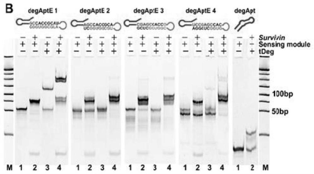
[0044] Embodiment 1: A degApt having a stem-loop conformation of the present invention is one of degAptE1, degAptE2, degAptE3, and degAptE4.
[0045] Wherein the nucleotide sequence of degAptE1 is shown in SEQ ID NO.1, specifically: GCU CGU UGA GCU CAUUAG CUC CGA GC C ACC GCA U GA AUG UAG AGA UGC GGU GGC.
[0046] The nucleotide sequence of degAptE2 is shown in SEQ ID NO.2, specifically: GCU CGU UGA GCU CAU UAGCUC CG A GC C ACC GCA GAA UGU AGA GA U GCG GUG GCU.
[0047] The nucleotide sequence of degAptE3 is shown in SEQ ID NO.3, specifically: GCU CGU UGA GCU CAU UAGCUC CGA GC C ACC G AA UGU AGA GAU GCG GUG G CU CG.
[0048] The nucleotide sequence of degAptE4 is shown in SEQ ID NO.4, specifically: GCU CGU UGA GCU CAU UAGC UC CGA GCC AC G AAU GUA GAG AUG CG G UGG CUC GGA.
[0049] Among them, GCU CGU UGA GCU CAU UAG CUC CGA GC is degApt, GA AUG UAG AGA UGCGGU GGC is the survivin mRNA recognition sequence, and the underlined part is th...
Embodiment 2
[0052] Example 2: A csiFP sensor of the present invention includes an RNA sensing module and a fluorescent protein reporter module fused with a degradant.
[0053] Wherein the RNA sensing module is degAptE 3 in Example 1, degAptE 3 has a stem-loop conformation, and its stem region is the key to binding with the Tat peptide-based degrader (tDeg).
[0054] The fluorescent protein reporter module is the fluorescent protein EGFP-tDeg fused with tDeg. The amino acid sequence of EGFP-tDeg is shown in SEQ ID NO.9. Among them, SGPRPRGTRGKGRRI: Tat peptide; RRRG: degradant; RPRGTRGKGR: nucleic acid sequence combined with the aptamer, the structural diagram is shown in image 3 .
[0055] The working principle of the csiFP sensor can be found in Figure 4 . It can be seen from the figure that when there is no target RNA (target survivin: GAC CAC CGC AUC UCU ACA UUC A), because the target RNA binding sequence expands degApt and destroys its active conformation, degApt loses the fluor...
Embodiment 3
[0062] Example 3: A csiFP sensor of the present invention includes an RNA sensing module and a fluorescent protein reporter module fused with a degradant. The RNA sensing module is a tRNA lys Scaffold-protected degAptE 3(tRNA lys -degAptE3), its nucleotide sequence is as shown in SEQ ID NO.5, specifically: (Double underlined part indicates degAptE 3 sequence, single underlined part indicates tRNA lys stand). The fluorescent protein reporter module is the fluorescent protein EGFP-tDeg fused with tDeg. Its preparation method is consistent with embodiment 2.
[0063] Experiment 2: Investigate the effect of stent protection.
[0064] Using tRNA in Example 3 lys - No tRNA in degAptE 3 and Example 1 lys Scaffold-protected degAptE 3 for fluorescence imaging of MCF-7 cells. See results Figure 7 .
[0065] Figure 7 For expression of EGFP-tDeg(none), expression of EGFP-tDeg and no tRNA lys Protected sensing module (noscaffold), expresses EGFP-tDeg and has tRNA lysFlu...
PUM
 Abstract
Description
Claims
Application Information
 - R&D
- Intellectual Property
- Life Sciences
- Materials
- Tech Scout
- Unparalleled Data Quality
- Higher Quality Content
- 60% Fewer Hallucinations
Browse by: Latest US Patents, China's latest patents, Technical Efficacy Thesaurus, Application Domain, Technology Topic, Popular Technical Reports.
© 2025 PatSnap. All rights reserved.Legal|Privacy policy|Modern Slavery Act Transparency Statement|Sitemap|About US| Contact US: help@patsnap.com


