
AC/DC resonant converter

A resonant converter, resonant tank technology, applied in the direction of converting DC power input to DC power output, AC power input converting to DC power output, instruments, etc. It can reduce the cost of components, improve the conversion efficiency, and reduce the switching loss.

Pending Publication Date: 2021-11-02
深圳崧盛创新技术有限公司
View PDF0 Cites 12 Cited by
  • Summary
  • Abstract
  • Description
  • Claims
  • Application Information

AI Technical Summary

Problems solved by technology

[0004] The two-stage AC / DC converter can achieve high power factor and reduce output ripple, but the number of components in the power conversion circuit and controller is large, resulting in high material costs
At the same time, the total output can only be obtained after the AC input undergoes two-stage power conversion, which will inevitably generate more power loss, and its conversion efficiency is the product of the conversion efficiency of PFC and DC / DC, so the overall conversion efficiency is low
When the boost PFC converter works at a lower AC input voltage, the increase in input current leads to an increase in its conduction loss, so the conversion efficiency in the low-voltage section of the wide input voltage range of 85 to 276Vac becomes lower
Although the turn-on loss of the LLC half-bridge resonant converter is low, when it works in a wide output voltage range, even if the DC bus voltage remains constant, the switching frequency will change greatly and deviate from its resonant frequency point, resulting in increased turn-off and conduction losses. High, so it is not suitable for wide output voltage occasions. In addition, two sets of independent controllers are required in the two-stage converter, the control method is complicated and there is a risk of instability

Method used


Image

  • AC/DC resonant converter
  • AC/DC resonant converter
  • AC/DC resonant converter

Examples


Embodiment Construction

[0077] Below, the present invention will be further described in conjunction with the accompanying drawings and specific implementation methods. It should be noted that, under the premise of not conflicting, the various embodiments described below or the technical features can be combined arbitrarily to form new embodiments. .

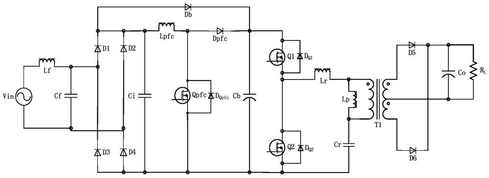
[0078] The development trend of switching power supply technology is high conversion efficiency, high power density and wide voltage range. The resonant converter has the inherent characteristics of zero voltage switching (ZVS) and zero current switching (ZCS), which can reduce switching loss and achieve higher conversion efficiency. Therefore, the switching frequency can be higher to reduce the volume of passive components and increase power density. Resonant converters generally adopt variable frequency control. When the input / output voltage or load changes, the switching frequency needs to be changed accordingly to adjust the voltage gain, and a hig...


PUM


Abstract

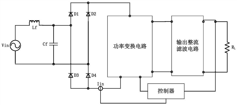
The invention provides an AC / DC resonant converter. A power conversion circuit is composed of basic switch units and a resonant tank, a controller adaptively controls the power conversion circuit according to different AC input voltages or different DC output voltages and switches the power conversion circuit into one or more basic switch units which are connected in series and in parallel and stacked to work and work in a high-frequency full-voltage control mode when alternating current input low voltage or direct current output high voltage exists, otherwise, work in a low-frequency partial-voltage control mode when alternating current inputs high voltage or direct current outputs low voltage, the two two-level control modes share the same set of resonant devices to simplify the design of a resonant tank, the controller is internally provided with a multiplier function unit, and the AC input current tracks the frequency and phase of the input voltage in real time so as to realize a power factor correction function. The AC / DC resonant converter directly converts the AC input instantaneous voltage into the DC output voltage, so that a conventional PFC converter and a DC bus capacitor thereof can be saved, the conversion efficiency is improved, and the component cost is reduced.

Description

technical field [0001] The invention relates to the technical field of switching power supplies, in particular to an AC / DC resonant converter. Background technique [0002] Switching power supply uses power switch tube to work at high frequency to realize AC / DC power conversion. It has the characteristics of small size, light weight, and high efficiency. It is widely used in industrial and civilian electronic equipment fields, such as chargers, power adapters, and LED drivers. , Industrial and control power supplies, etc., the relevant standards stipulate that switching power supplies above a certain output power need to have power factor correction (PFC) function. In the AC / DC power converter, the single-stage conversion structure is simple and the cost is low, but it cannot meet the requirements of high power factor (PF) and low ripple. At the same time, the power tube has the risk of excessive voltage or current stress. Therefore, two-stage converters are widely used in t...

Claims


Application Information

Patent Timeline
Patent Type & Authority Applications(China)
IPC IPC(8): H02M7/217H02M3/335H02M1/42H02M1/32
CPCH02M7/217H02M3/33569H02M3/33592H02M1/4241H02M1/32Y02B70/10
Inventor 袁源兰
Owner 深圳崧盛创新技术有限公司
Learn More