
Dielectric Filter with Orthogonal Resonator

A dielectric filter and resonant cavity technology, which is applied in the field of communication, can solve the problems of dielectric filter insertion loss and difficulty in realization, and achieve the effect of eliminating insertion loss and reducing insertion loss

Active Publication Date: 2022-03-29
PIVOTONE COMM TECH
View PDF8 Cites 0 Cited by
  • Summary
  • Abstract
  • Description
  • Claims
  • Application Information

AI Technical Summary

Problems solved by technology

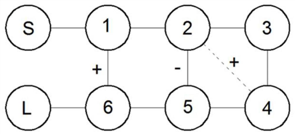
Among them, the coupling between each dielectric resonator can be divided into positive coupling (also called inductive coupling) and negative coupling (also called capacitive coupling) according to the polarity, and this type of dielectric filter realizes positive polarity Cross-coupling is easier, but cross-coupling with negative polarity is more difficult
[0004] In related technologies, a deep blind hole can be processed at a coupling window on the main road of the dielectric filter, which is equivalent to loading a large capacitor to achieve negative cross-coupling, and the blind hole causes the dielectric filter Insertion loss has a certain loss

Method used


Image

  • Dielectric Filter with Orthogonal Resonator
  • Dielectric Filter with Orthogonal Resonator
  • Dielectric Filter with Orthogonal Resonator

Examples


Embodiment Construction

[0028] In order to make the purpose, technical solutions and advantages of the embodiments of the present invention more clear, the implementation manners of the present invention will be further described in detail below in conjunction with the accompanying drawings.

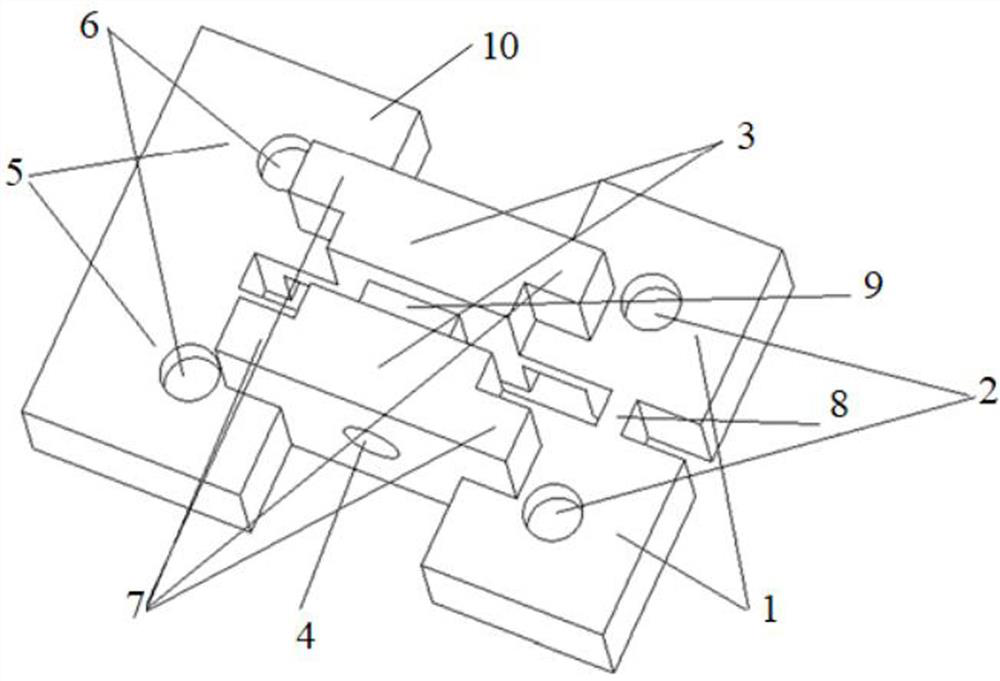
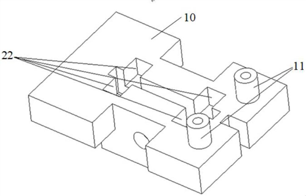
[0029] Please refer to figure 1 , which shows a dielectric filter with a quadrature resonant cavity provided by an embodiment of the present invention, and the dielectric filter includes a body 10 .

[0030] Wherein, the body 10 is made of a solid dielectric material with a high dielectric constant. Among them, ceramics have a higher dielectric constant, and the hardness and high temperature resistance of ceramics are also better, so the body 10 can be made of ceramic materials. Certainly, the solid dielectric material may also be other materials such as glass, which is not limited in this embodiment.

[0031] In this embodiment, six resonant cavities connected in sequence and arranged in two symmetrical rows...


PUM


Abstract

The invention discloses a dielectric filter with an orthogonal resonant cavity, which belongs to the technical field of communication. The dielectric filter includes a body; the body is loaded with six resonant cavities connected in sequence and symmetrically arranged in two rows; the first resonant cavity, the third resonant cavity, the fourth resonant cavity in the six resonant cavities The first resonant cavity and the sixth resonant cavity are located in the same plane; the second resonant cavity and the fifth resonant cavity in the six resonant cavities are perpendicular to the plane, and the second resonant cavity and the fifth resonant cavity are perpendicular to the plane. The coupling window between the fifth resonator is broadside coupling, which is used to achieve negative cross-coupling, which forms two transmission zeros. Broadside coupling in the present invention is negative cross-coupling, like this, does not need to adopt a very deep blind hole to realize negative cross-coupling, also just eliminated the insertion loss that this blind hole brings, thereby reduces the dielectric filter insertion loss.

Description

technical field [0001] Embodiments of the present invention relate to the field of communication technologies, and in particular to a dielectric filter with a quadrature resonant cavity. Background technique [0002] 5G (5 th Generation, the fifth generation mobile communication system) communication is the most cutting-edge communication technology at present, and various communication companies are competing to carry out related research. The Sub 6GHz segment in 5G communication adopts MIMO (Multi Input Multi Output) technology. Therefore, it is necessary to integrate a large number of filters inside the antenna, which poses a challenge to the insertion loss, out-of-band rejection, volume and weight of the filter. higher requirements. Traditional metal filters cannot be integrated inside the antenna due to their large size and weight, while dielectric filters can meet the needs of 5G systems. Therefore, dielectric filters are currently a hot research field. [0003] Th...

Claims


Application Information

Patent Timeline
Patent Type & Authority Patents(China)
IPC IPC(8): H01P1/212H01P1/20
CPCH01P1/212H01P1/2002
Inventor 江顺喜梁国春殷实项显杜锦杰
Owner PIVOTONE COMM TECH
Learn More