
Desulfurization, denitrification and dust removal integrated device and process for flue gas from glass kiln

A technology for desulfurization, denitrification and glass kiln, which is applied in the field of flue gas treatment, and can solve the problems of high temperature electrostatic precipitator efficiency difficult to achieve design efficiency, increase of catalytic ceramic membrane wall thickness, denitration catalyst deactivation and other problems

Active Publication Date: 2021-11-02
山东蓝繁环保科技有限公司
View PDF5 Cites 1 Cited by
  • Summary
  • Abstract
  • Description
  • Claims
  • Application Information

AI Technical Summary

Problems solved by technology

However, due to the particularity of the glass industry, that is, the dust particles are extremely small and have strong viscosity, there are some common problems in this process at present: 1) the efficiency of high-temperature electrostatic precipitator is difficult to reach the design efficiency; 2) due to the problem of high-temperature electrostatic precipitator The denitrification catalyst deactivates quickly, so that the denitrification operation cannot reach the design efficiency for several months; 3) There are two dust removal processes in this process, the bag dust removal system necessary for the electric dust removal process and dry desulfurization, so that the system is redundant and the equipment Occupies a large area, resulting in excessive investment and operating costs
At present, the integrated technology of desulfurization, denitrification and dust removal is mostly realized by catalytic ceramic membranes. In order to reduce the running resistance of catalytic ceramic membranes, the wall thickness of ceramic membranes generally does not exceed 1cm. The contact time between flue gas and catalytic ceramic membranes is too short, and nitrogen oxides cannot fully react.
The wall thickness of the catalytic ceramic membrane increases, and after the running resistance increases, the effect of reverse injection becomes worse, and the dust on the surface of the catalytic ceramic membrane cannot be effectively removed

Method used

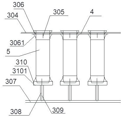

Image

  • Desulfurization, denitrification and dust removal integrated device and process for flue gas from glass kiln
  • Desulfurization, denitrification and dust removal integrated device and process for flue gas from glass kiln
  • Desulfurization, denitrification and dust removal integrated device and process for flue gas from glass kiln

Examples


Embodiment Construction

[0026] Embodiments of the present invention are described in detail below, examples of which are shown in the drawings, wherein the same or similar reference numerals designate the same or similar elements or elements having the same or similar functions throughout. The embodiments described below by referring to the figures are exemplary only for explaining the present invention and should not be construed as limiting the present invention.

[0027] In the description of the present invention, unless otherwise specified and limited, it should be noted that the terms "installation", "connection" and "connection" should be understood in a broad sense, for example, it can be mechanical connection or electrical connection, or two The internal communication of a component can be directly connected or indirectly connected through an intermediary. Those of ordinary skill in the art can understand the specific meanings of the above terms according to specific situations.

[0028] Su...


PUM

PropertyMeasurementUnit
Thicknessaaaaaaaaaa
Diameteraaaaaaaaaa

Abstract

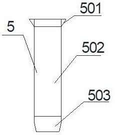
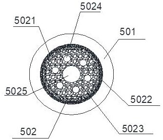
The invention discloses a desulfurization, denitrification and dust removal integrated device and process for flue gas from a glass kiln. The integrated device comprises a desulfurization and denitrification agent storage tank, a desulfurization and denitrification reactor, a blowing system, a tubesheet, a catalytic ceramic membrane, a transition bin and an ash conveying pipe, wherein the desulfurization and denitrification reactor comprises an upper box body, a middle box body and a lower box body, the tubesheet is located between the upper box body and the middle box body, the tubesheet is provided with tubesheet holes, the catalytic ceramic membrane comprises an expansion section, a catalytic main body and a supporting bottom, the catalytic main body comprises a filtering layer, a filtering catalytic layer, a main catalytic layer and a main clean gas channel from outside to inside, the thickness of the main catalytic layer is 3-10 cm, and auxiliary clean gas channels are distributed in the main catalytic layer. According to the desulfurization, denitrification and dust removal integrated device and process for the flue gas from the glass kiln, dust removal, desulfurization and denitrification can be completed in one device, the volume of glass kiln flue gas treatment equipment is greatly reduced, equipment investment is lowered, and desulfurization, denitrification and dust removal efficiency is improved.

Description

technical field [0001] The invention belongs to the technical field of flue gas treatment, and in particular relates to an integrated device and process for desulfurization, denitrification and dust removal of flue gas from a glass kiln. Background technique [0002] The flue gas in the glass industry has the characteristics of large flue gas volume and low concentration of dust, sulfur oxides, and nitrogen oxides. The current treatment process generally adopts the flue gas drawn from the first waste heat boiler at a temperature window of about 350°C and enters the high-temperature electrostatic precipitator The system removes dust, and then the flue gas enters the SCR denitrification system, under the action of the reducing agent NH3, NOx is reduced to N2 and H2O), the dust removal and denitrification standard flue gas then enters the second waste heat boiler to recover heat to about 120 ° C and enters the dry desulfurization device And finally discharged into the atmospher...

Claims


Application Information

Patent Timeline
IPC IPC(8): B01D46/00B01D46/54B01D53/60B01D53/86B01D53/75
CPCB01D46/0027B01D46/543B01D46/546B01D53/60B01D53/8631B01D53/869B01D2258/0283B01D2258/0241Y02A50/2351
Inventor 王兵
Owner 山东蓝繁环保科技有限公司
Learn More