Device and method for measuring pH of electrode solution interface

A technology for measuring electrodes and solutions. It is applied in the fields of measuring devices, electrochemical variables of materials, and material analysis by electromagnetic means. It can solve the problems of large size, special requirements for the shape of the measured metal electrode, and the lack of repeatability of experiments. To achieve the effect of simple composition, accurate measurement of pH value, and real-time monitoring

Pending Publication Date: 2021-10-29
INST OF OCEANOLOGY - CHINESE ACAD OF SCI
View PDF8 Cites 0 Cited by
  • Summary
  • Abstract
  • Description
  • Claims
  • Application Information

AI Technical Summary

Problems solved by technology

[0003] However, since the obvious change of pH at the interface of the metal solution under polarized conditions only occurs in a small area near the interface, the existing glass pH electrodes are not capable of measuring due to their large size, so tiny metal oxide electrodes are used as pH Sensors are extensively studied
At present, there are mainly two methods for the practical application of metal oxide electrodes in measuring interface pH. One is to place the metal oxide electrode around the metal electrode to be tested, and use a glass tube to isolate the metal electrode from the oxide electrode. The thickness of the tube wall controls the distance between the metal electrode and the metal oxide electrode. In this method, the preparation process of the metal iridium oxide electrode is complicated and the metal oxide electrode cannot be reused, so the experiment is not repeatable. The shape of the oxide electrode and the metal electrode to be tested is used to realize the close distance between the two. This method has special requirements for the shape of the metal electrode to be tested and is not suitable for large-scale applications.

Method used


Image

  • Device and method for measuring pH of electrode solution interface
  • Device and method for measuring pH of electrode solution interface
  • Device and method for measuring pH of electrode solution interface

Examples


Embodiment 1

[0041] The device for measuring the pH of the electrode solution interface is as Figures 1A-1E As shown, it includes electrolytic cell chamber A8, electrolytic cell chamber B12, glass salt bridge 6, saturated calomel electrode 7, proton exchange membrane 9, platinum wire 11, IrOx microelectrode 28 and insulating hollow screw 29, wherein the electrolytic cell chamber The two ends of the chamber A8 are respectively provided with a clamp A5 and a clamp B13, and the two ends of the electrolytic cell chamber A8 are respectively in sealing contact with the clamp A5 and the clamp B13; the two ends of the electrolytic cell chamber B12 are respectively provided with a clamp C14 and a clamp B13. Fixture D30, the two ends of the electrolytic cell chamber B12 are in sealing contact with the fixture C14 and the fixture D30 respectively, and the fixtures A5, B13, C14 and D30 are connected and fixed by a fixing device; the fixture A5, the fixture Both B13 and clamp C14 are provided with pas...

Embodiment 2

[0053] Adopt the method for above-mentioned device to measure metal electrode solution interface pH under the polarized condition, install by above-mentioned device, under the assistance of microscope, control metal electrode 3 surface and IrO by rotating insulating hollow screw rod 29 x The distance between the tips of the microelectrodes 28 is about 300 μm, and they are kept fixed. The medium solution to be measured is injected into the electrolytic cell chamber 8 and the electrolytic cell chamber 12 respectively, and the saturated calomel electrode 7 is used as a reference electrode, and the IrO x The microelectrode 28 is the working electrode to form a potential measurement system. The platinum wire 11 is used as the auxiliary electrode, the saturated calomel electrode 7 is used as the reference electrode, and the metal electrode 3 is used as the working electrode to form a polarization system. Constant polarization potential of -0.9V, continuous recording of IrO by data lo...

Embodiment 3

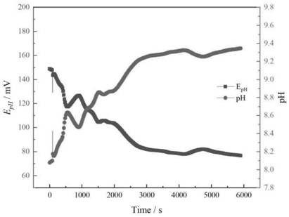
[0065] In this embodiment, the tested metal electrode material and the medium solution are the same as in Example 2, the difference is that the polarization potential applied to the tested metal electrode in this embodiment is -0.8V (vs. SCE), the test method and steps and implementation Example 2 is the same, the test results are as follows Figure 5 shown.

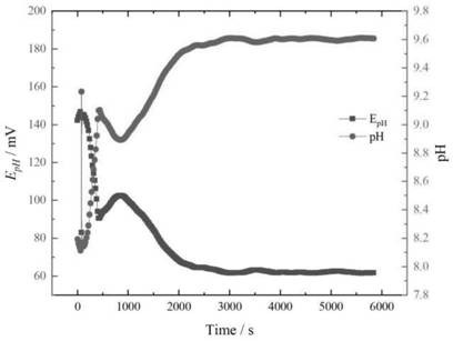
[0066] Depend on Figure 4 and Figure 5 It can be seen that the overall trend of the change of the pH value of the interface in the continuous test of nearly 100min is to rise rapidly first and then gradually reach a nearly steady state. The steady-state pH values ​​are 9.6 and 9.3, respectively. It can be seen that the more negative the polarization potential, the higher the pH value of the solution near the interface of the metal electrode under test.


PUM

PropertyMeasurementUnit
Diameteraaaaaaaaaa
Thicknessaaaaaaaaaa

Abstract

The invention relates to the field of metal corrosion, in particular to a device and a method for measuring pH of an electrode solution interface. The device comprises an electrolytic tank chamber A (8), an electrolytic tank chamber B (12), a glass salt bridge (6), a saturated calomel electrode (7), a proton exchange membrane (9), a platinum wire (11), an IrOx microelectrode (28) and an insulating hollow screw (29), the IrOx microelectrode (28) is installed at one end of the insulating hollow screw (29), and the distance between the IrOx microelectrode (28) and an electrode sample (3) is achieved by screwing the insulating hollow screw (29). Under a non-polarized or polarized condition, recording potential data of the IrOx microelectrode (28), and converting is carried out according to a Nernst equation to obtain an interface pH value of the medium solution to be detected. The device disclosed by the invention is simple in design and simple and convenient to operate, and can meet the requirement for measuring the pH in a near-interface solution micro region of the measured metal electrode under different polarization conditions.

Description

technical field [0001] The invention relates to a device for studying the interface pH in the field of metal corrosion, in particular to a device and a method for measuring the interface pH of an electrode solution. Background technique [0002] The corrosion of metals in aqueous solution is closely related to the pH of the metal solution interface. Usually, among the various factors affecting metal corrosion, most of the influencing factors affect the process of metal corrosion by changing the interface pH, such as pressure, biological adhesion, etc. , solution flow rate, etc. In particular, in order to inhibit metal corrosion, the most commonly used and most effective method in actual anticorrosion engineering is the cathodic protection method, which weakens the anodic reaction of metal dissolution by applying cathodic polarization potential or polarization current to the metal. During the application of cathodic protection, due to the occurrence of oxygen absorption reac...

Claims


Application Information

Patent Timeline
IPC IPC(8): G01N27/416G01N27/28G01N27/30G01N27/40
CPCG01N27/4167G01N27/28G01N27/302G01N27/40
Inventor 许勇黄彦良杨丹路东柱杨黎晖王秀通
Owner INST OF OCEANOLOGY - CHINESE ACAD OF SCI
Why Eureka
Try Eureka