Formula, preparation method and production device of wear-resistant flame-retardant PC material
A production device and formula technology, which is applied in the formulation of wear-resistant and flame-retardant PC materials, the preparation method and its production device, can solve the problems of affecting the air flow efficiency and high air flow resistance, so as to improve the dehumidification efficiency, ensure the quality of finished products, The effect of reducing drag
- Summary
- Abstract
- Description
- Claims
- Application Information
AI Technical Summary
Problems solved by technology
Method used
Image
Examples
preparation example Construction
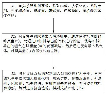
[0036] A preparation method of a wear-resistant and flame-retardant PC material, which is suitable for the formulation of the above-mentioned wear-resistant and flame-retardant PC material, comprising the following preparation steps:
[0037] S1: First, weigh PC material, antioxidant, heat stabilizer, bright lubricant, phase solvent, flame retardant, hydroxyl silicone oil, silicone and matrix resin according to the proportion requirements;
[0038] S2: Then first add the PC material into the dehumidifier, and dehumidify the gas derived from the PC material through the honeycomb plate 3 inside the dehumidifier, so that the moisture derived from the PC material condenses on the surface of the honeycomb plate 3, and then pass through the dehumidifier. Introduce hot gas to the guide to quickly remove the water inside the honeycomb plate 3;
[0039] S3: Add the dehumidified PC material into the heating and stirring machine, and then add antioxidants, heat stabilizers, bright lubric...
Embodiment 1
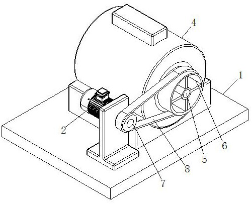
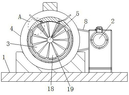
[0041] see Figure 2-8 As shown, a production device of wear-resistant and flame-retardant PC material is suitable for the preparation method of the above-mentioned wear-resistant and flame-resistant PC material, including a fixed seat 1, a motor 2 and a honeycomb plate 3; the fixed seat The top of 1 is fixedly connected with a conduction tube 4; the inside of the conduction tube 4 is rotatably connected with a mandrel 5; the surface of the mandrel 5 is provided with evenly arranged honeycomb discs 3; The first turntable 6 is fixedly connected; the top of the fixed seat 1 is fixedly connected with the motor 2; the output shaft of the motor 2 is fixedly connected with the second turntable 7; the connection between the second turntable 7 and the first turntable 6 There is a transmission belt 8; the sides of the honeycomb disc 3 are fixedly connected with a guide plate 9; the surface of the guide plate 9 is provided with uniformly arranged control grooves; the inside of the contr...
Embodiment 2
[0048] see Figure 9 As shown, the surface of the honeycomb plate 3 is provided with evenly arranged rotating grooves; the inside of the rotating grooves is connected with a switching plate 27; the switching plate 27 is designed with a 90-degree bending structure; the switching plate 27 Designed for a honeycomb structure; the inside of the rotating groove is provided with a pressure groove; the inside of the pressure groove is slidably connected with a pressure block 28, and the pressure block 28 is fixedly connected to the switching plate 27; during work, by setting the switching plate 27 , the inside of the pressure tank is connected to the air source, and by controlling the pressure of the air source, the pressure block 28 inside the pressure tank is ejected, and the pressure block 28 will drive the switch plate 27 to rotate, so that the switch plate 27 in the ninety-degree state rotates and cuts the ring , for the PC material with heavy moisture, the switching plate 27 sta...
PUM
 Abstract
Description
Claims
Application Information
 - R&D Engineer
- R&D Manager
- IP Professional
- Industry Leading Data Capabilities
- Powerful AI technology
- Patent DNA Extraction
Browse by: Latest US Patents, China's latest patents, Technical Efficacy Thesaurus, Application Domain, Technology Topic, Popular Technical Reports.
© 2024 PatSnap. All rights reserved.Legal|Privacy policy|Modern Slavery Act Transparency Statement|Sitemap|About US| Contact US: help@patsnap.com


