Tubular metal product polishing equipment
A metal product and tubular technology, which is applied in the field of tubular metal product polishing equipment, can solve problems such as impact, and achieve the effects of improving the collection effect, facilitating adjustment, and maintaining cleanliness
- Summary
- Abstract
- Description
- Claims
- Application Information
AI Technical Summary
Problems solved by technology
Method used
Image
Examples
Embodiment 1
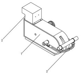
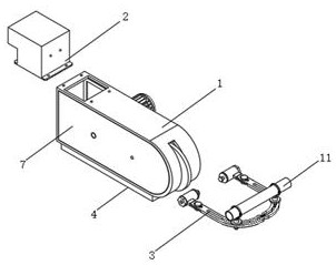
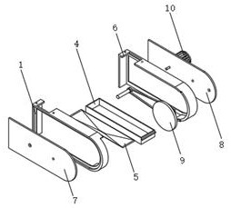
[0035] Such as figure 1 , 2, 3, 6, and 7, a tubular metal product polishing equipment, including a shell 1, a first side plate 7, a second side plate 8, a polishing structure 9, a drive motor 10, a straight pipe 11 and an elbow 12, the shell The first side plate 7 is connected to the opening on one side of the housing 1, and the second side plate 8 is connected to the opening on the other side of the housing 1. The front opening of the housing 1 is provided with a polishing structure 9, and one side of the second side board 8 A drive motor 10 is provided at the rear side, and the drive motor 10 is connected to the polishing structure 9 through a transmission mechanism, and the outer wall of the first side plate 7 and the second side plate 8 is connected with an adjustment structure 3, and the adjustment structure 3 is adapted to the polishing structure 9 A collection box 4 is connected to the opening of the lower end of the housing 1, and a special-shaped frame 5 is connected...
Embodiment 2
[0038] Such as figure 2 , 3 As shown in , 7 and 9, the air intake structure and the collection box assembly method of a tubular metal product polishing equipment, the L-shaped pipe 201 and the installation bar 202 are integrally arranged, and the threaded holes on the end surface of the installation bar 202 are aligned with the threaded holes on the shell 1 , the pipeline of the L-shaped tube 201 communicates with the inner cavity of the housing 1 through the first through hole 6, the L-shaped tube 201 is welded and fixed with the first bar 203 and the second bar 207, and the first bar 203 is connected with the first installation frame 204 bolt connection, the first installation frame 204 is connected to the fan 205 through the bracket, and the first installation frame 204 is bolted to the first filter screen 206, the second installation frame 208 is bolted to the second retaining strip 207, and the second installation frame 208 is bolted to the second filter screen 210, and...
Embodiment 3
[0040] Such as Figure 4 , 5 As shown, an adjustment structure of a tubular metal product polishing equipment, the adjustment structure 3 includes a fastening head 301, a first waist hole 302, a first arc bar 303, a second waist hole 304, a first connecting head 305, and a nut 306 , arc-shaped groove 307, U-shaped bar 308, second connecting head 309 and collar 310, and the outer wall of the first side plate 7 is connected with a fastening head 301, and the end surface of the protrusion on the side wall of the fastening head 301 is provided with a first waist hole 302, and the lower end of the protrusion on the side wall of the fastening head 301 is provided with a first arc bar 303, and one end of the first arc bar 303 is provided with a second waist hole 304, and the first waist hole 302 and the second waist hole A first connector 305 is inserted into the hole 304, a nut 306 is connected to the lower end of the first connector 305, an arc groove 307 is provided on the end su...
PUM
 Abstract
Description
Claims
Application Information
 - R&D Engineer
- R&D Manager
- IP Professional
- Industry Leading Data Capabilities
- Powerful AI technology
- Patent DNA Extraction
Browse by: Latest US Patents, China's latest patents, Technical Efficacy Thesaurus, Application Domain, Technology Topic, Popular Technical Reports.
© 2024 PatSnap. All rights reserved.Legal|Privacy policy|Modern Slavery Act Transparency Statement|Sitemap|About US| Contact US: help@patsnap.com


