High-power resonant switch
A high-power, switching technology, applied in the radio frequency field, can solve the problems of large RX insertion loss and achieve the effect of reconfigurable frequency
- Summary
- Abstract
- Description
- Claims
- Application Information
AI Technical Summary
Problems solved by technology
Method used
Image
Examples
Embodiment 1
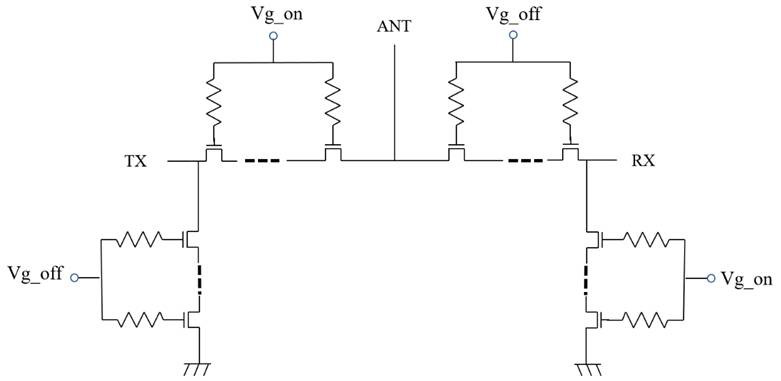
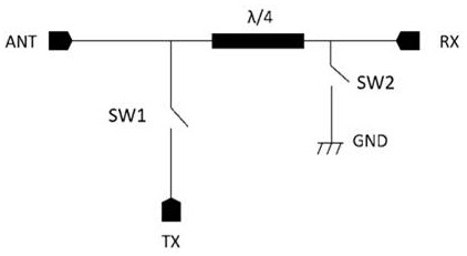
[0048] A high-power resonant switch of the present invention is based on the original high-power resonant switch, and a matching network is added at TX for optimization. For the specific structure, see Figure 5As shown, the high-power resonant switch includes: a transmitting branch and a receiving branch respectively connected to the ANT port;
[0049] The transmission branch includes a matching network N2, a switch SW1, and a transmission port TX; the transmission port TX is connected to the ANT port after the switch SW1 is connected in series; the electrical node between the transmission port TX and the switch SW1 is connected to the matching network N2 and then grounded;
[0050] The receiving branch includes a matching network N1, a switch SW2 and a receiving port RX; the receiving port RX is connected in series with the matching network N1 and then connected to the ANT port; the electrical node between the receiving port RX and the matching network N1 is connected to the ...
Embodiment 2
[0058] In order to solve the frequency hopping problem, the present invention is based on the form of the matching network N2 being a capacitor, and adds another ground-to-ground capacitor Ctx2 at the ANT-TX path series switch SW3 to form a reconfigurable high-power resonant switch. Its structure is as follows Image 6 shown.
[0059] According to the above analysis, the parallel connection of TX to the ground capacitor Ctx2 brings about a new parallel resonance. According to the parallel resonance formula , the larger the capacitance value C of the capacitor Ctx2 is, the lower the resonant frequency is, so the reconfigurability of the working frequency band can be realized by adjusting the capacitance value of the capacitor Ctx2 at TX. The specific analysis is as follows:
[0060] (a) When ANT-RX is in state: all switches are disconnected (OFF), at this time SW3 is equivalent to a capacitor (small capacitance value), and the capacitance of the newly introduced SW3 connecte...
Embodiment 4
[0067] In Embodiment 4, the matching network N2 includes an inductor Ltx1, an inductor Ltx2, and a switch SW3;
[0068] One end of the inductor Ltx1 is connected between the transmitting port TX and the switch SW1, and the other end of the inductor Ltx1 is grounded;
[0069] One end of the switch SW3 is connected between the transmitting port TX and the switch SW1, and the other end of the switch SW3 is connected in series with the inductor Ltx2 and grounded;
[0070] In the transmitting mode: in the high frequency band working mode, the switch SW1 and SW3 are closed, the switch SW2 is off, and the transmitting branch is turned on; in the low frequency band working mode, the switches SW1, SW2 and SW3 are closed, and the transmitting branch is turned on. Pass;
[0071] In the receiving mode, the switch SW1, the switch SW2, and the switch SW3 are all turned off, and the receiving branch is turned on.
[0072] SW3 can also be placed between SW1 and TX port (embodiment 5 such as...
PUM
 Abstract
Description
Claims
Application Information
 - R&D
- Intellectual Property
- Life Sciences
- Materials
- Tech Scout
- Unparalleled Data Quality
- Higher Quality Content
- 60% Fewer Hallucinations
Browse by: Latest US Patents, China's latest patents, Technical Efficacy Thesaurus, Application Domain, Technology Topic, Popular Technical Reports.
© 2025 PatSnap. All rights reserved.Legal|Privacy policy|Modern Slavery Act Transparency Statement|Sitemap|About US| Contact US: help@patsnap.com


