
Lubricating oil composition and lubricating oil defoaming method, and defoaming agent composition

A lubricating oil composition, lubricating oil base oil technology, applied in the direction of lubricating composition, chemical instruments and methods, separation methods, etc., can solve the problems of aggravated lubricating oil deterioration, lubricating performance, cooling efficiency reduction, metal surface wear, etc. Achieve the effect of suppressing the reduction of defoaming performance, suppressing separation and sedimentation

Active Publication Date: 2021-10-22
JXTJ NIPPON OIL & ENERGY CORP
View PDF12 Cites 0 Cited by
  • Summary
  • Abstract
  • Description
  • Claims
  • Application Information

AI Technical Summary

Problems solved by technology

If high-load operation and high-speed driving are continuously carried out, the foaming in the engine oil, transmission oil, or axle unit oil increases, and as a result, the following problems arise because the air bubbles are trapped in the hydraulic line : Poor control of oil pressure; reduced lubricating performance and cooling efficiency due to foaming; friction and galling of metal surfaces due to breakage of the oil film at the friction position; and deterioration of lubricating oil due to rise in oil temperature; Wait

Method used

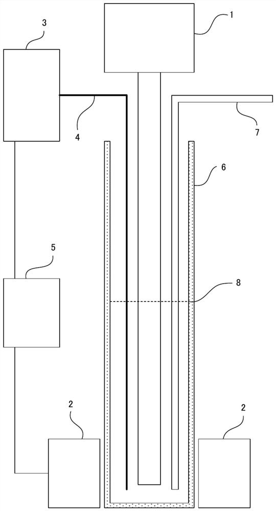

Image

  • Lubricating oil composition and lubricating oil defoaming method, and defoaming agent composition
  • Lubricating oil composition and lubricating oil defoaming method, and defoaming agent composition
  • Lubricating oil composition and lubricating oil defoaming method, and defoaming agent composition

Examples


Embodiment

[0543] Hereinafter, based on an Example and a comparative example, this invention is demonstrated more concretely. It should be noted that the purpose of the following examples is to illustrate the present invention and not to limit the present invention.

manufacture example

[0545] (Determination of molecular weight and molecular weight distribution)

[0546] In the following production examples and examples, the molecular weight and molecular weight distribution were obtained by using a GPC device (Tosoh Corporation) connected in series with three columns (TSK gel Super MultiPore HZ-M manufactured by Tosoh Corporation; inner diameter 4.6mm×15cm). HLC-8220), using tetrahydrofuran as the mobile phase, using a differential refractometer (RI) as the detector, under the conditions of measurement temperature 40°C, flow rate 0.35mL / min, sample concentration 1% by mass, and sample injection volume 5μL , measured using polystyrene as a standard substance.

manufacture example 1

[0548] The first antifoaming agent A-1 was produced according to the following operation steps.

[0549]Methyl isobutyl ketone (polymerization solvent) was introduced into a 500 mL four-necked flask equipped with a stirring paddle made of polytetrafluoroethylene (with a vacuum seal), a serpentine condenser, a three-way cock for nitrogen introduction, and a sample introduction port. ) 200 parts by mass, polysiloxane macromer represented by the following general formula (28) (manufactured by Shin-Etsu Chemical Co., Ltd.; weight average molecular weight 43,000; polydispersity index (Mw / Mn) 1.50) 5 parts by mass and formazan 95 parts by mass of lauryl acrylate, and after stirring to form a homogeneous mixture, the reaction system was vacuumed and purged with nitrogen 5 times using a diaphragm pump. Under nitrogen flow, as a free radical initiator, import MAIB (dimethyl 2,2'-azobisisobutyrate, 2,2'-azobisisobutyrate dimethyl from the sample introduction port: an azo radical polymer...


PUM

PropertyMeasurementUnit
depthaaaaaaaaaa
particle sizeaaaaaaaaaa
polydispersity indexaaaaaaaaaa

Abstract

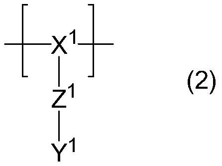
This lubricating oil composition contains a base oil of a lubricating oil, a first defoaming agent (A), and a second defoaming agent (B) which is a silicone-based defoaming agent. The first defoaming agent (A) is a first polymer (A1) or a second polymer (A2), or a combination thereof. The first polymer (A1) includes: a first polymer chain including a polysiloxane structure represented by general formula (1) and having a degree of polymerization of 5-2000; and a second polymer chain that includes a repeating unit represented by general formula (2) and that is bound to the first polymer chain. The second polymer (A2) is a copolymer of a first monomer component represented by general formula (7) or (8) and a second monomer component represented by general formula (9).

Description

technical field [0001] The invention relates to a lubricating oil composition, a method for defoaming lubricating oil, and a defoaming agent composition. Background technique [0002] In various mechanical devices, lubricating oil is used to improve the lubricity between parts. At this time, if the foaming of the lubricating oil worsens, poor lubrication, poor oil pressure control, and reduced cooling efficiency may result, so it is necessary to suppress foaming in the lubricating oil. [0003] For example, in recent years, in automobile engines, transmissions, and axle units, the conditions to which lubricating oils are exposed have become more severe along with their higher performance and lower energy consumption. If high-load operation and high-speed driving are continuously carried out, the foaming in the engine oil, transmission oil, or axle unit oil increases, and as a result, the following problems arise because the air bubbles are trapped in the hydraulic line : P...

Claims


Application Information

Patent Timeline
Patent Type & Authority Applications(China)
IPC IPC(8): B01D19/04C10N20/02C10N20/04C10N30/18C10N40/04C10N40/25C10M155/02
CPCC10M155/02C10N2040/04C10N2040/08C10N2040/25C10N2030/18C10M2229/041C10M2203/1025C10N2030/02C10M157/10C10M2205/0285C10M2207/2805C10M2209/084C10M2215/28C10M2219/044C10N2030/68C10N2020/04B01D19/0005B01D19/02B01D19/0409C10M2229/051C10N2020/02C10N2070/02C10N2040/042B01D19/0427C10M101/02C10M105/32C10M111/02C10M169/041C10M177/00C10M2203/1006
Inventor 高木彰辰巳刚菖蒲纪子
Owner JXTJ NIPPON OIL & ENERGY CORP
Learn More