Charging input protection device and charging overvoltage and over-temperature protection method thereof

A technology of input voltage and charging input, which is applied in the field of pet training products, and can solve problems such as damage to the voltage regulator tube, failure of subsequent stage circuit protection, breakdown damage, etc.

Pending Publication Date: 2021-10-22
SHENZHEN PATPET TECH CO LTD
View PDF0 Cites 2 Cited by
  • Summary
  • Abstract
  • Description
  • Claims
  • Application Information

AI Technical Summary

Problems solved by technology

However, it takes a certain amount of time for the voltage stabilizing device to stabilize from high voltage to low voltage. During this voltage stabilizing process, some voltage-sensitive electronic components in the back-end electronic products may be damaged by breakdown and cannot be fully and effectively protected.
[0006] In addition, the voltage stabilizing device needs to consume power when stabilizing the voltage. If the power consumption is greater than the rated power consumption of the voltage stabilizing device, the voltage stabilizing diode will be damaged by open circuit or short circuit, and the subsequent circuit cannot be protected.
In addition, although some products also have a protective switch on the positive line, when the positive and negative poles of the charger are reversed, it is still possible for the charged electronic product to be connected to live or leakage or static electricity, resulting in damage (such as figure 2 shown)

Method used


Image

  • Charging input protection device and charging overvoltage and over-temperature protection method thereof
  • Charging input protection device and charging overvoltage and over-temperature protection method thereof
  • Charging input protection device and charging overvoltage and over-temperature protection method thereof

Examples


Embodiment 1

[0050] Embodiment 1: the concrete structure of the present invention is as follows:

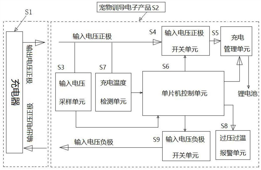
[0051] Please refer to the attached image 3 , a charging input protection device of the present invention, comprising a charger S1, an electronic product S2 that can be plugged with the charger S1 to form a charging state, the circuit board of the electronic product S2 has a charging protection circuit, and the charging protection Circuit includes:

[0052] There is a single-chip microcomputer control unit S6 for judging whether the input voltage is within a preset voltage range, the single-chip microcomputer control unit S6 is connected to the positive input voltage of the charging input port through an input voltage positive pole switch unit S4, and the single-chip microcomputer control unit S6 can control the input voltage. On-off of the positive voltage switch unit S4, the single-chip microcomputer control unit S6 is also connected to the negative input voltage of the charging input por...

Embodiment 2

[0058] Such as Figure 4 As shown, a preferred technical solution of this embodiment: the anode of the input voltage of the charging input port is connected in series with a PMOS transistor Q4, and the anode of the input voltage of the charging input port is connected to the drain D of the PMOS transistor Q4;

[0059] The negative input voltage of the charging input port is connected in series with a PMOS transistor Q5, and the negative input voltage of the charging input port is connected to the drain D of the PMOS transistor Q5;

[0060] A series resistor R53 and a resistor R54 are connected between the drain D of the PMOS transistor Q4 and the drain D of the PMOS transistor Q5, and the circuit node between the resistor R53 and the resistor R54 is connected to the The first AD detection port of the single-chip microcomputer control unit S6;

[0061] The gate G of the PMOS transistor Q4 and the gate G of the PMOS transistor Q5 are respectively electrically connected to the s...

Embodiment 3

[0065] Such as Figure 3-4 As shown, a charging overvoltage and overtemperature protection method, the method is:

[0066] 1. A single-chip microcomputer control unit S6 is installed on the circuit board of the electronic product S2, which is connected to and controlled by a charging management unit S5 and an overvoltage and overtemperature alarm unit S8;

[0067] 2. The input voltage positive pole of the charging input port of the electronic product S2 and the input voltage negative pole of the charging input port are respectively connected with the input voltage positive pole switching unit S4 and the input voltage negative pole switching unit S9, and the single-chip microcomputer control unit S6 controls the input voltage positive pole switching unit On-off of S4 and input voltage negative switch unit S9;

[0068] 3. The input voltage positive pole of the charging input port of the electronic product S2 is connected to the input voltage sampling unit S3, and the sampling v...


PUM


Abstract

The invention discloses a charging input protection device and a charging overvoltage and over-temperature protection method thereof. The device comprises a charger and a charging protection circuit, and the charging protection circuit comprises a single-chip microcomputer control unit and an input voltage sampling unit. The single-chip microcomputer control unit is connected to an input voltage positive electrode of the charging input port and can control on-off of the input voltage positive electrode switch unit. The single-chip microcomputer control unit is further connected to an input voltage negative electrode of the charging input port and can control on-off of the input voltage negative electrode switch unit. A sampling terminal of the input voltage sampling unit is connected to an input voltage positive electrode, a sampling voltage output end of the input voltage sampling unit is connected to the single-chip microcomputer control unit, and the input voltage sampling unit is used for sampling input voltage, connected to a charged electronic product, of the charger and sending the collected voltage to the single-chip microcomputer control unit. According to the invention, damage to power supply of a rear-end circuit due to misuse of an overvoltage adapter can be effectively and reliably avoided.

Description

technical field [0001] The invention relates to pet training products, in particular to a charging input protection device and a charging overvoltage and overtemperature protection method for the device. Background technique [0002] At present, after many rechargeable electronic products are returned from after-sales or end users, it is found through analysis that the reason is that the product is damaged by an adapter exceeding its rated charging voltage. Because the adapters have different nominal output voltages, for example, the common ones are 5V for mobile phone adapters, 9V for digital camera adapters, 12V for router adapters, and 18V for vacuum cleaner adapters. But the charging port of these chargers is often used the same. Many consumers can’t tell the difference or don’t know how to use it. It’s possible to use an adapter with a high output voltage to charge a product with a low input voltage. For example, use an adapter above 9V to directly charge a 5V electron...

Claims


Application Information

Patent Timeline
Patent Type & Authority Applications(China)
IPC IPC(8): H02J7/00H02H7/18
CPCH02J7/0034H02J7/00308H02J7/00309H02J7/007182H02J7/007192H02H7/18
Inventor 易丽兰李清辉
Owner SHENZHEN PATPET TECH CO LTD
Why Eureka
Try Eureka