A high-voltage dynamic voltage restorer thyristor bypass valve backup trigger protection and state monitoring system and its application method

A technology of a condition monitoring system and an application method, applied in the direction of automatic disconnection of emergency protection devices, circuit devices, emergency protection detection, etc., can solve the problem of reducing the reliability and availability indicators of DVR devices, damaging DVR inverters and sensitive load equipment. , Unable to monitor the key components and functions of the valve group, so as to avoid long-term energization, avoid device damage, and improve accuracy

Active Publication Date: 2022-01-04
普世通(北京)电气有限公司
View PDF9 Cites 0 Cited by
  • Summary
  • Abstract
  • Description
  • Claims
  • Application Information

AI Technical Summary

Problems solved by technology

At present, the high-voltage DVR thyristor bypass valve has a simple structure, only has the function of continuous flow, and has a low degree of automation. It cannot monitor the key components and functions of the valve group, and does not have a protection function. After the device fails, it cannot be found in time, and it will operate with a fault for a long time. The reliability and availability index of the DVR device is reduced, and in severe cases, the DVR converter and sensitive load equipment will be damaged, which is unacceptable

Method used


Image

  • A high-voltage dynamic voltage restorer thyristor bypass valve backup trigger protection and state monitoring system and its application method
  • A high-voltage dynamic voltage restorer thyristor bypass valve backup trigger protection and state monitoring system and its application method
  • A high-voltage dynamic voltage restorer thyristor bypass valve backup trigger protection and state monitoring system and its application method

Examples


Embodiment Construction

[0028] Below in conjunction with accompanying drawing, the present invention is described in further detail:

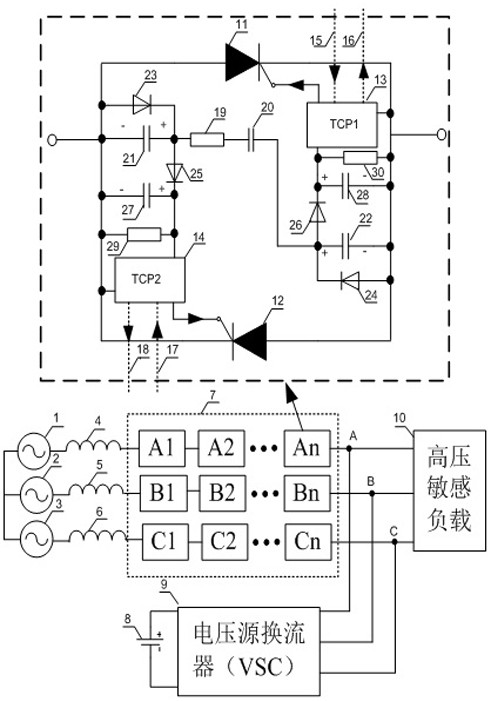
[0029] A high-voltage DVR thyristor bypass valve backup trigger protection and state monitoring system is composed as follows: high-voltage A-phase voltage source (1), high-voltage B-phase voltage source (2), high-voltage C-phase voltage source (3), system A equivalent value reactance (4), system B equal value reactance (5), system C equal value reactance (6), high voltage DVR thyristor bypass valve (7), DC energy storage components (8), DVR voltage source converter VSC (9 ), high voltage sensitive load (10).

[0030] According to attached figure 1 Shown:

[0031] The high-voltage DVR thyristor bypass valve (7) is composed of 3n thyristor stages, of which A phase is composed of A1, A2...An total of n thyristor stages in series, and B phase is composed of B1, B2...Bn total of n thyristor stages The stages are connected in series, and phase C consists of n thyristor ...


PUM


Abstract

The invention provides a high-voltage DVR thyristor bypass valve backup trigger protection and state monitoring system and method thereof. The high-voltage DVR thyristor bypass valve is composed of 3n thyristor stages, and receives the pulse detection signal sent by the upper-level controller in one cycle. Based on the pulse signal returned by the high-voltage DVR thyristor bypass valve, the upper-level controller judges the working status of the thyristor level, so as to realize the functions of thyristor level status monitoring, precise fault location and backup protection triggering.

Description

technical field [0001] The invention belongs to the field of smart grids, in particular to a high-voltage DVR thyristor bypass valve backup trigger protection and state monitoring system and an application method thereof. Background technique [0002] With the development of science and technology and the expansion of industrial scale, the electricity consumption of various sectors of the economy continues to increase, and more and more users adopt high-tech equipment with good performance and high efficiency but are sensitive to changes in power characteristics, such as: robots, automation Production lines, precision CNC machine tools, high-precision measuring instruments and computer information management systems, etc. These systems and equipment are very sensitive to various disturbances of the power grid, and any power quality problem may cause major economic losses and bring adverse social impacts. More than 90% of user complaints about power quality problems involve ...

Claims


Application Information

Patent Timeline
Patent Type & Authority Patents(China)
IPC IPC(8): H02H1/00H02H7/20H02H3/05H02J13/00H02J3/12
CPCH02H1/0007H02H7/20H02H3/05H02J13/00017H02J3/12Y04S10/20Y02E60/00Y04S40/124
Inventor 渠学景李建丁小刚黄新宇陈伟
Owner 普世通(北京)电气有限公司
Why Eureka
Try Eureka