
PI parameter setting method of motor controller, control system and storage device

A motor controller and parameter tuning technology, applied in control systems, vector control systems, motor generator control and other directions, can solve the problems of large debugging workload, large calculation amount, complex modeling of high-level control objects, etc. Increased workload and stability

Pending Publication Date: 2021-10-12
AUTOCHIPS WUHAN CO LTD
View PDF1 Cites 0 Cited by
  • Summary
  • Abstract
  • Description
  • Claims
  • Application Information

AI Technical Summary

Problems solved by technology

[0003] For different motor control systems, there are usually three methods for PI parameter tuning: one is manual tuning, that is, the trial and error method, through artificially building a test environment, and manually adjusting to find the PI parameters suitable for the current system, so as to confirm the current loop in the motor control system. and the PI parameter size of the speed loop, so that the motor control system can work normally, but the debugging workload is large, time-consuming and labor-intensive; the second is based on the pole configuration method of the high-order control object, that is, the relevant physical characteristics of the actual system are reflected through the high-order object model , so as to determine the PI parameters of the system, but the modeling of high-order control objects is complex, and the controller parameters need to be determined through simulation analysis, and the practical effect is not good; the third is the mixed tuning method of PI parameters, that is, through the phase angle margin and closed-loop bandwidth To determine the PI parameters of the system and the stability and response speed of the system, but the calculation is complex and the amount of calculation is large

Method used


Image

  • PI parameter setting method of motor controller, control system and storage device
  • PI parameter setting method of motor controller, control system and storage device
  • PI parameter setting method of motor controller, control system and storage device

Examples


Embodiment Construction

[0013] The solutions of the embodiments of the present application will be described in detail below in conjunction with the accompanying drawings.

[0014] In the following description, for purposes of illustration rather than limitation, specific details, such as specific system architectures, interfaces, and techniques, are set forth in order to provide a thorough understanding of the present application.

[0015] The terms "system" and "network" are often used interchangeably herein. The term "and / or" in this article is just an association relationship describing associated objects, which means that there can be three relationships, for example, A and / or B can mean: A exists alone, A and B exist simultaneously, and there exists alone B these three situations. In addition, the character " / " in this article generally indicates that the contextual objects are an "or" relationship. In addition, "many" herein means two or more than two.

[0016] see figure 1 , figure 1 It ...


PUM


Abstract

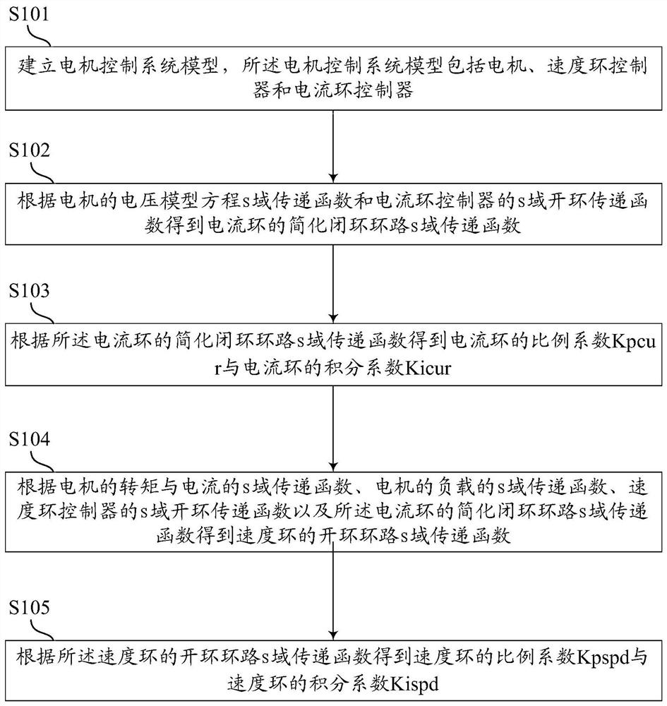
The invention discloses a PI parameter setting method of a motor controller, a control system and a storage device. The PI parameter setting method of the motor controller comprises the following steps: establishing a motor control system model comprising a motor, a speed loop controller and a current loop controller; obtaining a simplified closed loop s-domain transfer function of the current loop according to the voltage model equation s-domain transfer function of the motor and the s-domain open-loop transfer function of the current loop controller; obtaining a proportionality coefficient and an integral coefficient of the current loop according to the simplified closed loop s-domain transfer function of the current loop; and deducing an open-loop s-domain transfer function of the speed loop through the simplified closed-loop s-domain transfer function of the current loop so as to obtain a proportionality coefficient and an integral coefficient of the speed loop. According to the scheme, the PI parameter can be deduced and calculated through a formula, and the workload of setting the PI parameter by the motor controller is reduced.

Description

technical field [0001] The present application relates to the technical field of motor control, in particular to a method for setting PI parameters of a motor controller, a control system, and a storage device. Background technique [0002] Motors are widely used in high-performance servo systems due to their small size, high power density, and high efficiency. The design of the controller parameters of the motor control system greatly affects the system performance. The controller of the motor control system includes a current loop controller and a speed loop controller. The current loop controller realizes the rapid following of the inner loop current, which is the basis for the normal operation of the outer loop, and the speed loop controller is the key link to realize the excellent speed regulation performance of the system. Therefore, to improve the performance of the controller, it is necessary to set the optimal PI parameters to meet the requirements of the correspo...

Claims


Application Information

Patent Timeline
Patent Type & Authority Applications(China)
IPC IPC(8): H02P21/00H02P21/18H02P21/22
CPCH02P21/0017H02P21/18H02P21/22
Inventor 卜学龙
Owner AUTOCHIPS WUHAN CO LTD
Learn More