Built-in permanent magnet synchronous motor sensorless parameter error compensation strategy

A permanent magnet synchronous motor and sensor parameter technology, which is applied in the control of generators, motor control, motor generator control, etc., can solve the problems that are easily affected by flux linkage, inductance parameter changes and system delay, and achieve robustness The effect of improving and improving the accuracy of position estimation

Active Publication Date: 2021-10-08
XIAN UNIV OF TECH
View PDF6 Cites 2 Cited by
  • Summary
  • Abstract
  • Description
  • Claims
  • Application Information

AI Technical Summary

Problems solved by technology

The rotor position estimation accuracy and closed-loop robustness of these two methods depend on the accuracy of the flux linkage amplitude and angle, and are extremely susceptible to flux linkage, inductance parameter changes, and system delays.

Method used


Image

  • Built-in permanent magnet synchronous motor sensorless parameter error compensation strategy
  • Built-in permanent magnet synchronous motor sensorless parameter error compensation strategy
  • Built-in permanent magnet synchronous motor sensorless parameter error compensation strategy

Examples


Embodiment Construction

[0060] The present invention will be described in detail below in conjunction with the accompanying drawings and specific embodiments.

[0061] A parameter error compensation strategy for a built-in permanent magnet synchronous motor without a position sensor according to the present invention is specifically implemented according to the following steps:

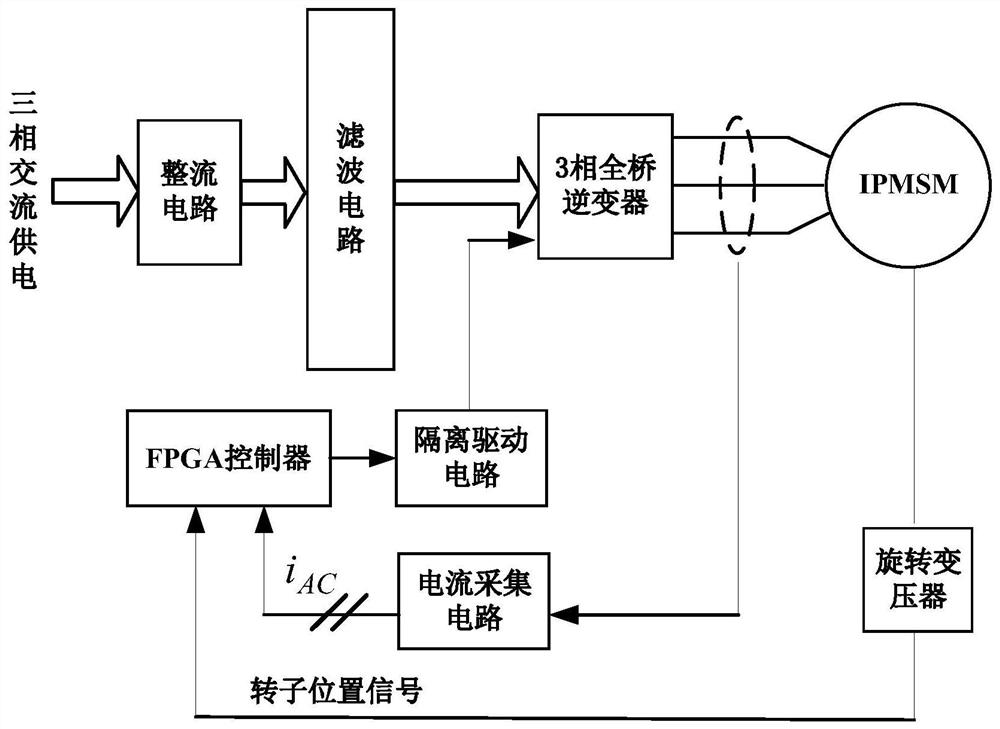
[0062] Step 1, based on the indirect calculation method of flux linkage, estimate the MT shaft current and replace the estimated value with a given flux linkage, so as to improve the rotor position estimation based on flux linkage, the principle block diagram is as follows figure 1 As shown, the specific steps are as follows:

[0063] Step 1.1, for the three-phase current i A i B i C Sampling is performed, and Clarke transformation is performed on it to obtain the α-axis and β-axis currents, and then the estimated value of the stator flux linkage angle is calculated and the electromagnetic torque estimate As shown in ...


PUM


Abstract

The invention discloses a built-in permanent magnet synchronous motor sensorless parameter error compensation strategy. The strategy specifically comprises the steps of carrying out the estimation of an MT shaft current based on a flux linkage indirect calculation method, replacing an estimation value with a given flux linkage, and improving the flux linkage-based rotor position estimation, acquiring deviation coefficients mu and lambda, correcting permanent magnet flux linkage and quadrature-axis inductance parameters online in real time, and using the corrected parameters for calculation of the maximum torque current ratio control stator flux linkage given value of the motor, MT-axis current estimation and load angle calculation. The invention provides a parameter error compensation strategy forbuilt-in permanent magnet synchronous motor sensorless control under the low switching frequency SHEPWM modulation, which can correct the permanent magnet flux linkage and quadrature axis inductance parameter deviation in real time, thereby improving the rotor position estimation precision and enhancing the system robustness.

Description

technical field [0001] The invention belongs to the technical field of transmission control of AC motors, and in particular relates to a parameter error compensation strategy for a built-in permanent magnet synchronous motor without a position sensor. Background technique [0002] With the rapid development of high-speed rail trains, permanent magnet synchronous traction motors with wide speed range, high power density and low energy consumption have become a research hotspot in the field of rail transit, and the existing EMU train traction systems are all using mechanical position / speed sensor to obtain the position or speed signal of the motor. During the actual operation of high-speed trains, the electromagnetic environment is complex and the vibration is severe, which can easily lead to the failure of mechanical sensors and cause traction system failures, resulting in large torque shocks, and damage to key components such as bearings, gears, and motors in severe cases, ...

Claims


Application Information

Patent Timeline
IPC IPC(8): H02P21/00H02P21/14H02P21/18H02P21/24H02P25/022
CPCH02P21/14H02P21/18H02P21/24H02P21/0003H02P25/022H02P2207/05
Inventor 张航梁文睿张辉
Owner XIAN UNIV OF TECH
Why Eureka
Try Eureka