Straight groove flow guide staggered dotting pipe

A technology of straight shape and tube body, which is applied in the field of heat dissipation pipes, can solve the problems of failing to meet the heat dissipation requirements of radiators, the heat dissipation pipes do not have the turbulence effect, and the pressure resistance of the pipe body is not enhanced, so as to improve the heat dissipation adaptability , increase the pressure resistance and save cost

Pending Publication Date: 2021-10-08
NANNING ANHE MECHANICAL EQUIP CO LTD
View PDF0 Cites 0 Cited by
  • Summary
  • Abstract
  • Description
  • Claims
  • Application Information

AI Technical Summary

Problems solved by technology

[0004] 1. The existing heat dissipation pipes only increase the pressure resistance on both sides of the pipe body, and the pressure resistance of the pipe body as a whole is not enhanced, resulting in that when the heat dissipation pipe is assembled into a radiator or a radiator and other heat dissipation devices, Because the overall pressure resistance of the pipe body is not high, it is easy to cause deformation of the pipe body and affect the heat dissipation effect;
[0005] 2. There is no spoiler effect in the existing heat dissipation pipe, and the heat dissipation performance is poor, which cannot meet the heat dissipation requirements of the existing radiator

Method used


Image

  • Straight groove flow guide staggered dotting pipe
  • Straight groove flow guide staggered dotting pipe

Examples


Embodiment Construction

[0022] In order to make the object, technical solution and advantages of the present invention clearer, the present invention will be described in further detail below with reference to the accompanying drawings and preferred embodiments. However, it should be noted that many of the details listed in the specification are only for readers to have a thorough understanding of one or more aspects of the present invention, and these aspects of the present invention can be implemented even without these specific details.

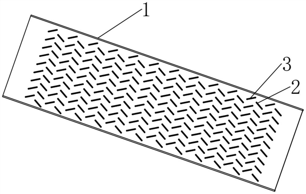
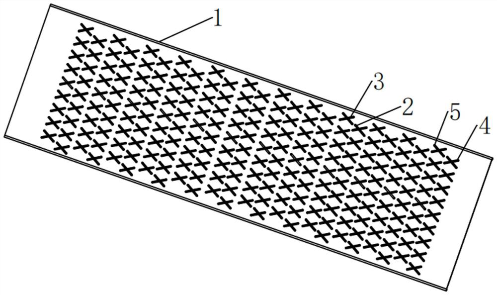
[0023] Such as Figure 1-2 As shown, according to a straight groove diversion dislocation dotting pipe of the present invention, the straight groove diversion dislocation dotting pipe includes a pipe body, and the nozzle height of the pipe body is 1.4 mm. The upper side of the pipe body is provided with a plurality of first straight grooves and a plurality of second straight grooves, the first straight grooves and the second straight grooves are formed by inward ...


PUM


Abstract

The invention discloses a straight groove flow guide staggered dotting pipe, and belongs to the technical field of heat dissipation pipes. The staggered dotting pipe comprises a pipe body, wherein first straight grooves and second straight grooves are formed in the upper side face of the pipe body, third straight grooves and fourth straight grooves are formed in the lower side face of the pipe body, the multiple first straight grooves, the multiple second straight groove rows, the multiple third straight groove rows and the multiple fourth straight groove rows form the first straight groove rows, the second straight groove rows, the third straight groove rows and the fourth straight groove rows correspondingly, the first straight grooves and the third straight grooves are arranged in a staggered and crossed mode, the outer side walls of the bottoms of the first straight grooves abut against the outer side walls of the bottoms of the third straight grooves, the second straight grooves and the fourth straight grooves are arranged in a staggered and crossed mode, and the outer side walls of the bottoms of the second straight grooves abut against the outer side walls of the bottoms of the fourth straight grooves. The grooves in different directions are formed in the upper side face and the lower side face, so that a plurality of S-shaped circulation paths are formed in the pipe body, the heat dissipation effect of the pipe body is improved, and the turbulent flow effect is achieved.

Description

technical field [0001] The invention relates to the technical field of radiating pipes, in particular to a pipe with a straight groove diversion misalignment. Background technique [0002] With the rapid development of the automobile industry, the functionality and complexity of vehicles are increasing day by day, and the radiator structure is becoming more and more complex. The radiator usually needs to be assembled with the electronic fan, condenser, intercooler and car body at the same time. During assembly, Often, the radiator is deformed due to insufficient pressure resistance of the radiating pipe in the radiator, which affects the heat dissipation effect. [0003] In the existing heat dissipation pipe, reinforcing sheets are added to the pipe body to increase the pressure resistance on both sides of the pipe body. The existing heat dissipation pipe has the following disadvantages: [0004] 1. The existing heat dissipation pipes only increase the pressure resistance o...

Claims


Application Information

Patent Timeline
Patent Type & Authority Applications(China)
IPC IPC(8): F28F1/00F28F9/24
CPCF28F1/00F28F9/24
Inventor 沈平黄乃玉梁立兴林健麦云锋
Owner NANNING ANHE MECHANICAL EQUIP CO LTD
Why Eureka
Try Eureka