Melt-blown fiber production mechanism

A melt-blown fiber and melt-blown technology is applied in the field of melt-blown fiber production mechanisms, which can solve the problems of reduced winding and storage speed of melt-blown fabrics, heat accumulation of melt-blown fabrics, and increased contact time, etc., to avoid heat accumulation and to achieve a degree of automation High, increase the effect of contact time

Active Publication Date: 2021-09-17
江苏柏琳家用纺织品有限公司
View PDF7 Cites 2 Cited by
  • Summary
  • Abstract
  • Description
  • Claims
  • Application Information

AI Technical Summary

Problems solved by technology

[0004] The purpose of the present invention is to provide a melt-blown fiber production mechanism, which can automatically adjust the blanking distance of the spinneret once the spinning speed of the discharge hole on the melt-blown machine body increases, so that the final blanking speed can be changed, and at the same time The winding speed of the rewinding roller for the melt-blown fabric is reduced, so that the melt-blown fabric can increase the contact time with the air, and the heat carried on it is transferred to the air, which solves the problem of manually adjusting the spacing of the spinning and blanking. It is time-consuming and laborious, and the efficiency is low, and it is difficult to integrate the blanking speed with the winding speed of the melt-blown cloth, which may easily lead to heat accumulation of the rolled-up melt-blown cloth, which brings inconvenience to use

Method used


Image

  • Melt-blown fiber production mechanism
  • Melt-blown fiber production mechanism
  • Melt-blown fiber production mechanism

Examples


Embodiment Construction

[0024] The following will clearly and completely describe the technical solutions in the embodiments of the present invention with reference to the accompanying drawings in the embodiments of the present invention. Obviously, the described embodiments are only some, not all, embodiments of the present invention. Based on the embodiments of the present invention, all other embodiments obtained by persons of ordinary skill in the art without making creative efforts belong to the protection scope of the present invention.

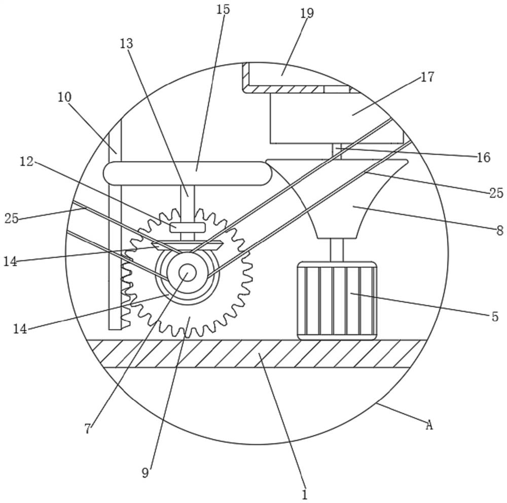
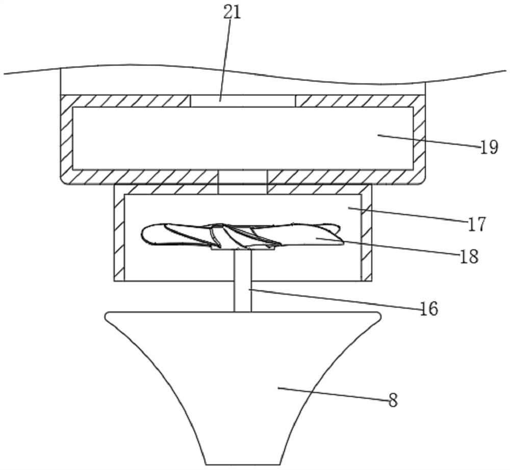
[0025] see Figure 1 to Figure 4 , the present invention provides a technical solution: a melt-blown fiber production mechanism, including a housing 1, a winding roller 2 and a melt-blown machine body 3, the inner wall of the housing 1 is provided with two pulleys-4, and fixedly connected There is a motor 5 and a telescopic drive part, a belt 6 is connected between the two pulleys 4, the meltblown body 3 is fixedly connected to the telescopic part of the teles...


PUM


Abstract

The invention discloses a melt-blown fiber production mechanism, and relates to the technical field of melt-blown cloth fiber production equipment. The melt-blown fiber production mechanism comprises a shell, a wind-up roller and a melt-blown machine body, wherein the inner wall of the shell is further rotationally connected with a transmission shaft through a fixed shaft; and the surface of the transmission shaft is in transmission connection with the wind-up roller and any one belt pulley I through a transmission part and synchronously rotates with the wind-up roller and any one belt pulley I. The melt-blown fiber production mechanism further comprises a monitoring component for detecting the spinning speed of the melt-blowing machine body, and an auxiliary component I for automatically reducing the rotating speed of the transmission shaft along with increase of the spinning speed of the melt-blowing machine body, wherein the monitoring component is in signal connection with a telescopic driving component; and the auxiliary component I is in transmission connection with a motor. The melt-blown fiber production mechanism provided by the invention has the advantages that once the spinning speed of a discharge hole in the melt-blowing machine body is increased, the spinning blanking distance can be automatically adjusted, the final blanking speed is changed, meanwhile, the winding storage speed of the wind-up roller on the melt-blowing cloth is reduced, the contact time of the melt-blowing cloth and air can be prolonged, and heat carried by the melt-blowing cloth is transferred into the air.

Description

technical field [0001] The invention relates to the technical field of melt-blown cloth fiber production equipment, in particular to a melt-blown fiber production mechanism. Background technique [0002] Melt-blown nonwovens are manufactured using molds. The production process is to use high-melt index raw materials, heat and pressurize them into a molten state through a screw extruder, pass through the mold, and the melt distribution channel reaches the spinneret hole at the front end of the nozzle. After extrusion, it is stretched by two convergent high-speed and high-temperature air streams to make it thinner. After passing through a certain height, it is sprayed onto the fabric splicing machine, and the thinned fibers are cooled and solidified on the mesh curtain device to form a melt-blown nonwoven fabric. [0003] In the actual production process, in order to increase the strength and elongation, the hot air flow rate or temperature is generally increased, so the spinn...

Claims


Application Information

Patent Timeline
Patent Type & Authority Applications(China)
IPC IPC(8): D01D5/098D01D5/088D04H1/56B65H18/10
CPCD01D5/0985D01D5/088D04H1/56B65H18/10
Inventor 黄俊盈
Owner 江苏柏琳家用纺织品有限公司
Why Eureka
Try Eureka