
Manufacturing method of stamping formed part, and stamping formed part

A technology of stamping forming and manufacturing method, which is applied in the field of stamping and forming parts and stamping-forming parts manufacturing, can solve the problems of reducing the manufacturing efficiency of stamping and forming parts, save the operation of hole flanging and shaping, reduce the difference of force, and enhance the The effect of suitability

Pending Publication Date: 2021-09-17
殷胜男
View PDF1 Cites 1 Cited by
  • Summary
  • Abstract
  • Description
  • Claims
  • Application Information

AI Technical Summary

Problems solved by technology

The die set uses the forming process of narrow-body stamping parts, which can improve the positioning accuracy and processing accuracy of narrow-body stamping parts in the process of processing, and through optimizing the structure, transforming the complexity of cutting, improving the quality of processing; but in this technical solution After completing the processing in the trimming and punching composite mold, when flanging and shaping the punching part, it is also necessary to change the mold to the punching and shaping composite mold, and the mold changing operation reduces the manufacturing efficiency of stamping formed parts

Method used


Image

  • Manufacturing method of stamping formed part, and stamping formed part
  • Manufacturing method of stamping formed part, and stamping formed part
  • Manufacturing method of stamping formed part, and stamping formed part

Examples


Embodiment approach

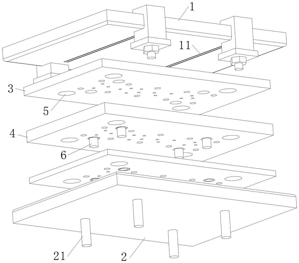
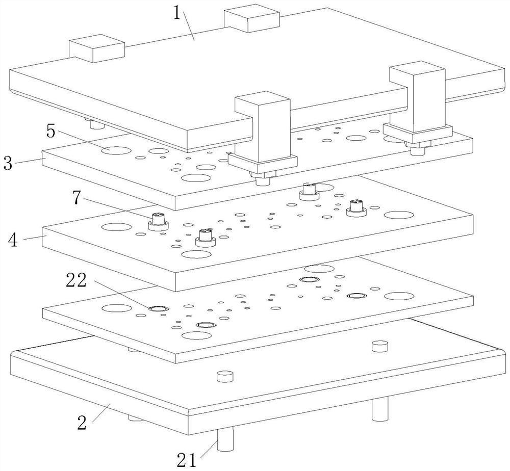
[0038] As an embodiment of the present invention, a pair of electromagnets 72 magnetically repelling each other are fixedly connected to both ends of the pocket spring 7 , and a pair of electrode pieces are fixedly connected to the electromagnet 72 at the end of the pocket spring 7 toward the upper mold base 1 721, the electrode sheet 721 protrudes from the surface of the pocket spring 7; the surface of the upper mold base 1 is provided with an electrode groove 11, and the electrode groove 11 is in electrical contact with the electrode sheet 721; during the manufacturing process of the stamped part, By setting the electromagnets 72 at both ends of the pocket spring 7 to magnetically repel each other, by controlling the magnitude of the connected current, the parameters of different stamping pressures are satisfied, and at the same time, the pocket spring 7 with a relatively large deformation is contracted in the positioning hole 5, The distance between the electromagnets 72 is ...


PUM


Abstract

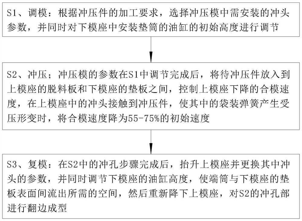
The invention relates to the technical field of stamping, in particular to a manufacturing method of a stamping formed part, and the stamping formed part. The manufacturing method comprises the steps of die adjusting, stamping and die copying, and a used stamping die comprises an upper die holder, a lower die holder and a controller; due to the fact that the deformation condition of a board in the forming process is complex and is changed with contact between the board and a die surface, main stress parameters in the board surface of each part of a blank are further dynamically changed, and consequently drawing defects generated in the stamping process are difficult to prejudge; and the quality of a formed part is affected. Therefore, a quick connector is arranged and used for fixedly connecting an insert; insert parameters for stamping the formed part are easy to adjust, and stress difference of the insert acting on different parts of the formed part in the stamping process is adjusted by the aid of a bagged spring mounted at the tail end of the insert; the stress difference borne by drawing of the formed part is reduced through the deformation quantity of the bagged spring; and the surface quality of the formed part is maintained, and therefore the manufacturing quality of the stamping formed part is improved.

Description

technical field [0001] The invention relates to the technical field of stamping, in particular to a method for manufacturing a stamped formed part and a stamped formed part. Background technique [0002] Stamping parts are formed by applying external force to plates, strips, pipes and profiles by presses and molds to cause plastic deformation or separation, so as to obtain workpieces of required shape and size; compared with other mechanical processing methods , Stamping has many unique advantages both in terms of technology and economy. For parts with more complex shapes, when using stamping technology, according to the processing requirements of the formed parts, the processing process includes a separation process and a forming process. First In the separation process, the workpiece is punched and blanked, and then the workpiece is shaped through the forming process, and finally the required stamped formed part is obtained. [0003] When stamping the cover with a relativ...

Claims


Application Information

Patent Timeline
Patent Type & Authority Applications(China)
IPC IPC(8): B21D35/00B21D37/02B21D37/16
CPCB21D35/001B21D35/002B21D37/02B21D37/16
Inventor 殷胜男陆军
Owner 殷胜男
Learn More