Melt-blown non-woven fabric reinforcing and forming equipment
A technology of melt-blown non-woven fabrics and fabrics, which is applied in the direction of non-woven fabrics, textiles, and papermaking, and can solve problems that affect the reinforcement production effect, affect the uniformity of non-woven reinforcement, and product wrinkles
- Summary
- Abstract
- Description
- Claims
- Application Information
AI Technical Summary
Problems solved by technology
Method used
Image
Examples
Embodiment 1
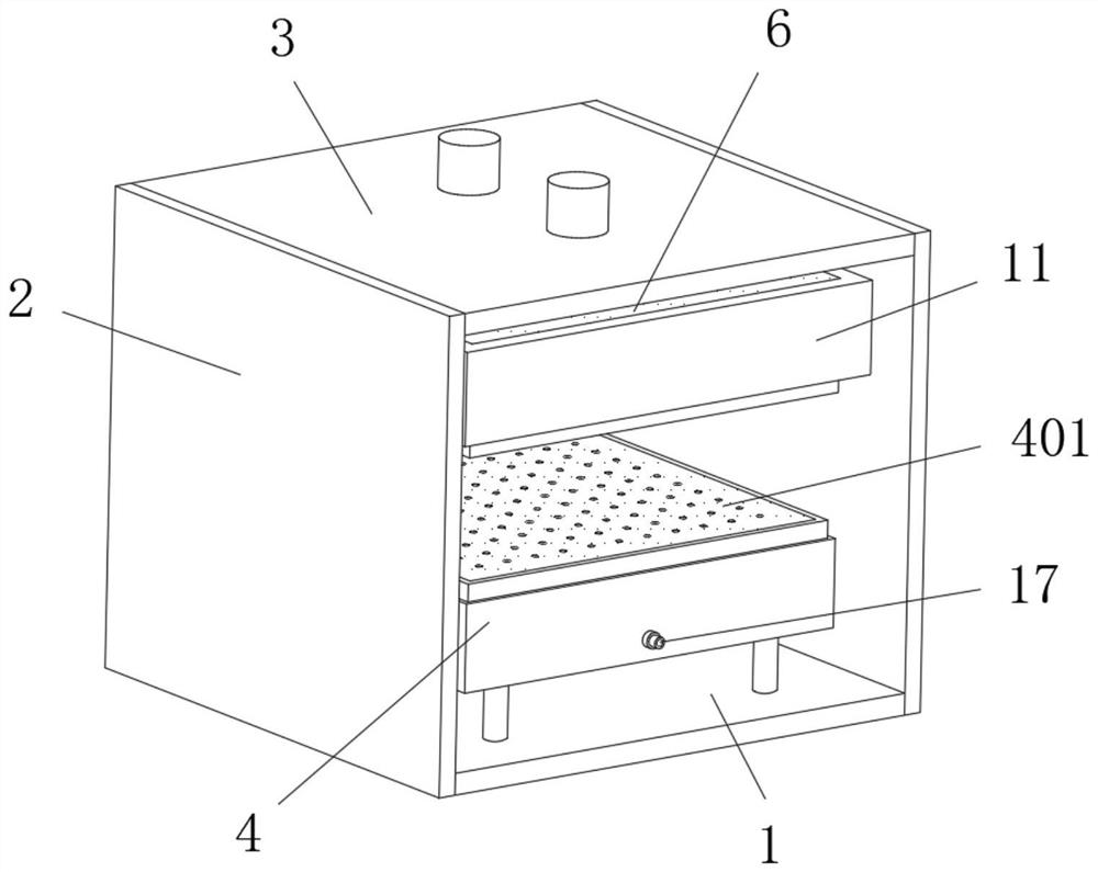
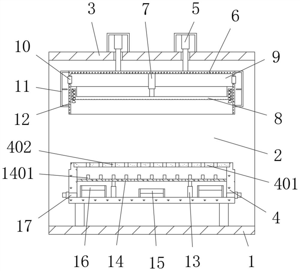
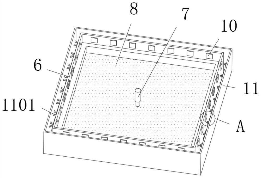
[0031] refer to Figure 1-7 , a meltblown non-woven fabric strengthening equipment, including a fixing mechanism, the bottom and top of the fixing mechanism are respectively provided with a placement mechanism and a hot pressing mechanism, the hot pressing mechanism is arranged in the fixing mechanism to vertically lift, and the hot pressing mechanism is set The limit seat 6 placed horizontally, the limit seat 6 is set as a box-shaped structure with an open bottom, the middle position of the inner wall of the top of the limit seat 6 is fixed with a second electric push rod 7, and the bottom end of the second electric push rod 7 A heat-pressing part 8 is fixed to be slidably connected to the inner wall of the limiting seat 6. The heat-pressing part 8 is arranged in a box-like structure with an open top, and a heat exchange chamber 9 is formed between the top of the heat-pressing part 8 and the limiting seat 6;
[0032] The outer wall of the limit seat 6 is wrapped and fixed wit...
Embodiment 2
[0039] Embodiment 2 includes all structures and methods of Embodiment 1, with reference to Figure 1-9 , a kind of melt-blown non-woven fabric strengthening equipment, also includes, the placement mechanism is provided with a placement seat 4 fixed on the outer wall of the top of the base 1, and the top of the outer wall of the placement seat 4 is provided with a bottom end of the inner wall of the limit seat 6. Adapted fastening groove, the top outer wall of the placement seat 4 is provided with a limiting groove, the bottom inner wall of the limiting groove is provided with an airflow cavity, the inner wall of the limiting groove is placed with a placement plate 401, and the top of the placement plate 401 is provided with multiple ventilation The hole 402 is connected with the air guide tube 17 at the bottom of the air flow chamber.
[0040] In the present invention, both sides of the inner wall at the bottom of the air flow cavity are fixed with a second electric push rod 1...
PUM
 Abstract
Description
Claims
Application Information
 - R&D
- Intellectual Property
- Life Sciences
- Materials
- Tech Scout
- Unparalleled Data Quality
- Higher Quality Content
- 60% Fewer Hallucinations
Browse by: Latest US Patents, China's latest patents, Technical Efficacy Thesaurus, Application Domain, Technology Topic, Popular Technical Reports.
© 2025 PatSnap. All rights reserved.Legal|Privacy policy|Modern Slavery Act Transparency Statement|Sitemap|About US| Contact US: help@patsnap.com


