Screw drill motor stator manufacturing and forming machining machine and machining method

A motor stator and forming processing technology, which is applied in the manufacture of tools, metal processing equipment, and stator/rotor body manufacturing, can solve the problems of reducing the effect of grinding, not being able to replace the grinding mechanism, and reducing the flexibility of the machine.

Active Publication Date: 2021-09-14
YANCHENG XINYONGJIA PETROLEUM MACHINERY MFG
View PDF10 Cites 5 Cited by
  • Summary
  • Abstract
  • Description
  • Claims
  • Application Information

AI Technical Summary

Problems solved by technology

[0003] At present, the existing machines usually have the following deficiencies when grinding the surface of the inner wall of the stator of the screw drilling tool motor: 1. The existing machines can only grind the inner wall of the stator of the same specification, and cannot grind the inner wall of the stator within a certain range. The diameter of the stator can be adjusted accordingly, so that the inner wall of the stator of diffe...

Method used


Image

  • Screw drill motor stator manufacturing and forming machining machine and machining method
  • Screw drill motor stator manufacturing and forming machining machine and machining method
  • Screw drill motor stator manufacturing and forming machining machine and machining method

Examples


Embodiment Construction

[0039] The embodiments of the present invention will be described in detail below with reference to the accompanying drawings, but the present invention can be implemented in many different ways defined and covered by the claims.

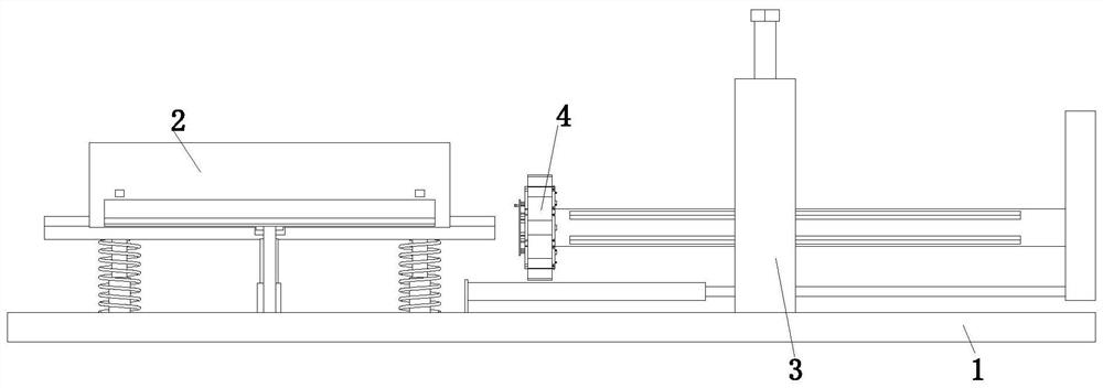
[0040] Such as Figure 1 to Figure 11 As shown, a screw drilling tool motor stator manufacturing molding processing machine, including a bottom plate 1, a placement device 2, a driving device 3 and a grinding device 4, the upper end of the bottom plate 1 is sequentially installed with a placement device 2 and a driving device from left to right 3. The outer surface of the driving device 3 is rotatably connected with the grinding device 4 through the bearing near the left end.

[0041] The placement device 2 includes a sliding frame 21, a limit rod 22, a limit spring 23, a rectangular rod 24, an arc plate 25, a spring telescopic rod 26, a cylinder 27 and a clamping mechanism 28, and the upper end of the base plate 1 is installed There is a sliding f...


PUM


Abstract

The invention relates to a screw drill motor stator manufacturing and forming machining machine and machining method. The screw drill motor stator manufacturing and forming machining machine comprises a bottom plate, a placing device, a driving device and a grinding device, wherein the placing device and the driving device are sequentially installed at the upper end of the bottom plate from left to right, and the portion, close to the left end, of the outer surface of the driving device is rotatably connected with the grinding device through a bearing. By means of the screw drill motor stator manufacturing and forming machining machine and machining method, the problems that when an existing machine conducts surface grinding on the inner walls of screw drill motor stators, inner wall grinding can only be conducted on the stators of the same specification generally, corresponding adjustment cannot be conducted within a certain range according to the diameters of the inner walls of the stators, thus the inner walls of the stators of different sizes cannot be ground, the mechanical use flexibility is reduced, corresponding adjustment cannot be conducted according to the radians of arc-shaped protrusions on the inner walls of the stators, thus grinding effects are reduced, moreover, a grinding mechanism cannot be replaced, thus the grinding effects of the grinding machine after long-term use are reduced, and the like can be solved.

Description

technical field [0001] The invention relates to the technical field of drilling tool production, in particular to a manufacturing and forming processing machine and processing method for a motor stator of a screw drilling tool. Background technique [0002] The screw drilling tool is a volumetric downhole power drilling tool that uses drilling fluid as the power and converts the fluid pressure energy into mechanical energy. The working principle of the screw drilling tool is that the mud pumped by the mud pump flows through the bypass valve and enters the motor. A certain pressure difference is formed between the inlet and outlet, which drives the rotor to rotate around the axis of the stator, and transmits the speed and torque to the drill bit through the cardan shaft and the transmission shaft, so as to realize the drilling operation; the screw drilling tool is mainly composed of a bypass valve, a motor, a universal The motor consists of four major assemblies, including th...

Claims


Application Information

Patent Timeline
IPC IPC(8): B24B21/00B24B21/02B24B21/18B24B41/06B24B41/04H02K15/02
CPCB24B21/004B24B21/008B24B21/02B24B21/18B24B41/067B24B41/04H02K15/02
Inventor 张国旗叶俊杰席文奎徐永和刘华文王涛
Owner YANCHENG XINYONGJIA PETROLEUM MACHINERY MFG
Why Eureka
Try Eureka