
Chip mounter suction nozzle coaxiality error automatic calibration method based on machine vision

A machine vision, automatic calibration technology, applied in the direction of electrical components, electrical components, electrical components assembling printed circuits, etc., can solve problems such as difficulty in ensuring consistency, affecting placement accuracy, and changes in mechanical positioning accuracy.

Active Publication Date: 2021-09-10
CHANGZHOU MINGSEAL ROBOT TECH CO LTD
View PDF3 Cites 0 Cited by
  • Summary
  • Abstract
  • Description
  • Claims
  • Application Information

AI Technical Summary

Problems solved by technology

When mounting on the placement machine, it is generally necessary to install a buffer device at the nozzle to reduce the impact on the mounted workpiece due to the difference in the height of the workpiece during the placement. The advantage of this design is that it is low in cost and easy to use. However, the accuracy of the machine after assembly is easily affected by the verticality of the installation and the concentricity of the suction nozzle caused by machining errors, and the consistency is difficult to guarantee
In addition, during the placement process of the existing placement machine, due to the fast movement speed and high frequency of use of the placement head nozzle during the work process, and the unsmooth impact will inevitably occur during the suction and placement process Therefore, after working for a long time, the mechanical positioning accuracy of the placement head is prone to large changes, which affects its placement accuracy. Users need to frequently replace the placement head and adjust the parameters of the machine, resulting in poor overall experience of the machine.

Method used


Image

  • Chip mounter suction nozzle coaxiality error automatic calibration method based on machine vision
  • Chip mounter suction nozzle coaxiality error automatic calibration method based on machine vision
  • Chip mounter suction nozzle coaxiality error automatic calibration method based on machine vision

Examples


Embodiment Construction

[0024] In order to make the technical problems, technical solutions and beneficial effects solved by the present invention clearer, the present invention will be further described in detail below in conjunction with the accompanying drawings and embodiments. It should be understood that the specific embodiments described here are only used to explain the present invention, not to limit the present invention.

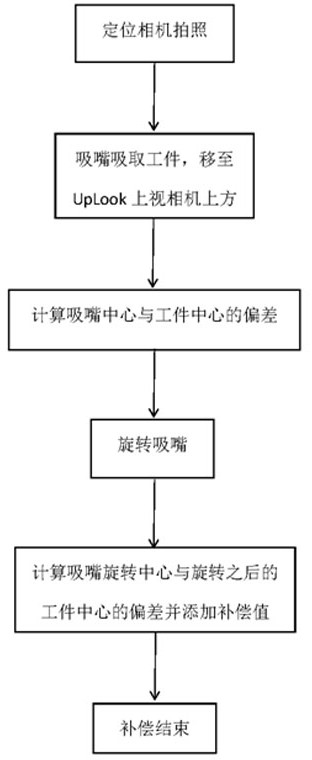
[0025] See figure 1 , a method for automatic calibration of the coaxiality error of the chip mounter nozzle based on machine vision of the present invention, the specific steps are as follows:

[0026] Step 1. First, perform a mechanical return to zero on the rotation axis of the suction nozzle on the placement head, and ensure that this position is used as a reference point for compensation every time. The role of the rotary axis of the suction nozzle is illustrated as an example. The suction nozzle picks up the workpiece and corrects the angular deviation between the ...


PUM


Abstract

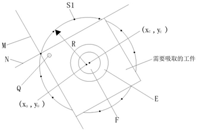
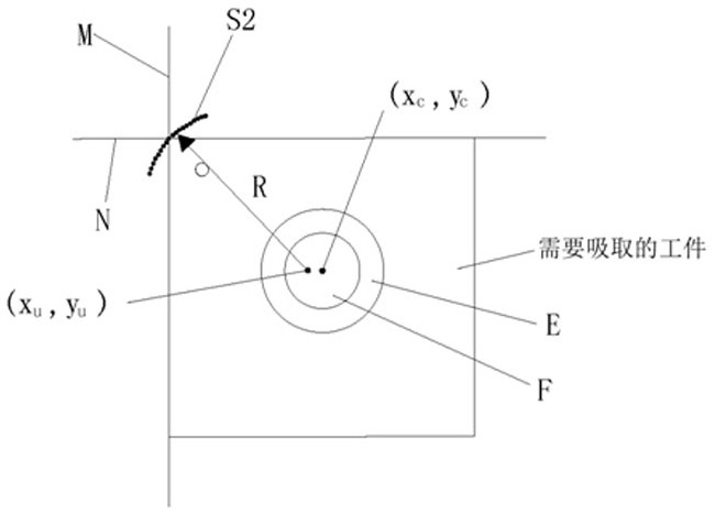
The invention discloses a chip mounter suction nozzle coaxiality error automatic calibration method based on machine vision. The method comprises the steps of obtaining the Mark information of a product through a CCD positioning camera, and enabling a suction nozzle to be positioned at the position of the product, sucking a product, then moving the product to the position above an UpLook up-looking camera to shoot once every other angle, acquiring image information, conducting fitting on the obtained position information of each Mark of the material according to the image information, and calculating the rotation center of a mechanical shaft, calculating the distances from the Mark points to the rotation center of the product in the rotation process, solving the average value of all the distances, subtracting the calculated average value from the distances from all the Mark points to the rotation center to obtain a value, namely the concentricity deviation caused by rotation of the suction nozzle in the mounting process, and compensating and correcting the concentricity deviation. According to the chip mounter suction nozzle coaxiality error automatic calibration method, it is guaranteed that the concentricity of each time of machining is within an allowable range, and the mounting precision is guaranteed.

Description

technical field [0001] The invention relates to the technical field of chip mounter mounting, in particular to a machine vision-based automatic calibration method for the coaxiality error of the chip mounter suction nozzle. Background technique [0002] In the production line, the placement machine is configured after the dispenser or screen printing machine. The placement machine is a device that accurately places surface mount components on a fixed position by moving the placement head. When mounting on the placement machine, it is generally necessary to install a buffer device at the nozzle to reduce the impact on the mounted workpiece due to the difference in the height of the sucked workpiece during placement. The advantage of this design is that it is low in cost and easy to use. However, the accuracy of the machine after assembly is easily affected by the verticality of the installation and the concentricity of the suction nozzle caused by machining errors, and the co...

Claims


Application Information

Patent Timeline
IPC IPC(8): H05K3/30H05K13/00H05K13/04
CPCH05K3/30H05K13/0015H05K13/0404
Inventor 罗文查进陈辉曲东升冀伟李长峰张文晔
Owner CHANGZHOU MINGSEAL ROBOT TECH CO LTD
Learn More