
Double-turbine direct-driven permanent magnet synchronous generator set

A technology of permanent magnet synchronous and generator sets, which is applied in electric components, ocean energy power generation, engine components, etc., and can solve problems such as high sealing performance requirements, increased manufacturing costs, and large structures

Pending Publication Date: 2021-09-10
SHANDONG UNIV
View PDF12 Cites 0 Cited by
  • Summary
  • Abstract
  • Description
  • Claims
  • Application Information

AI Technical Summary

Problems solved by technology

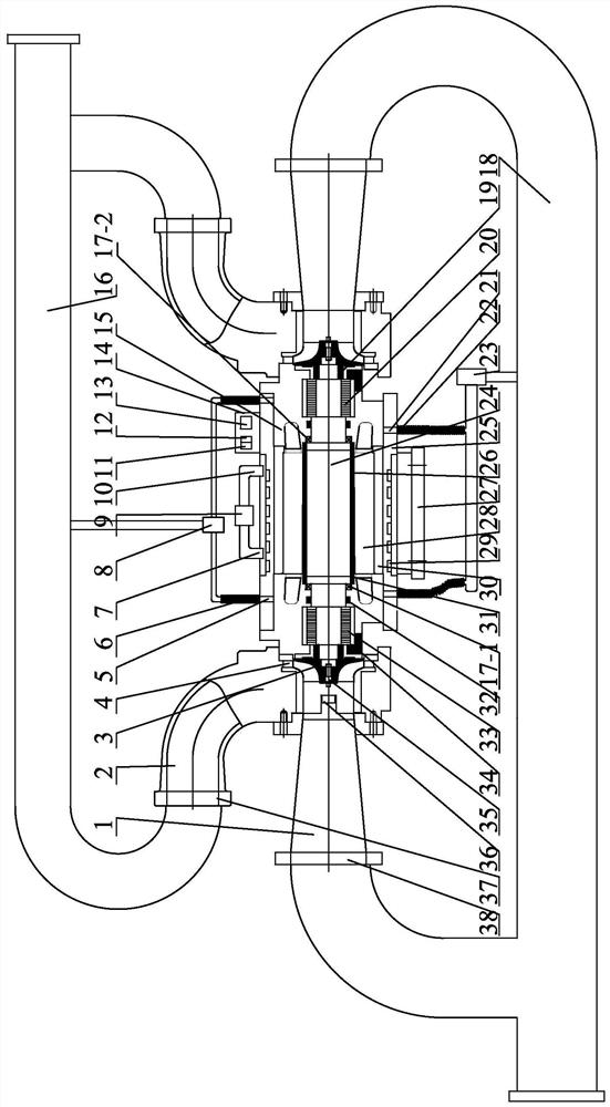
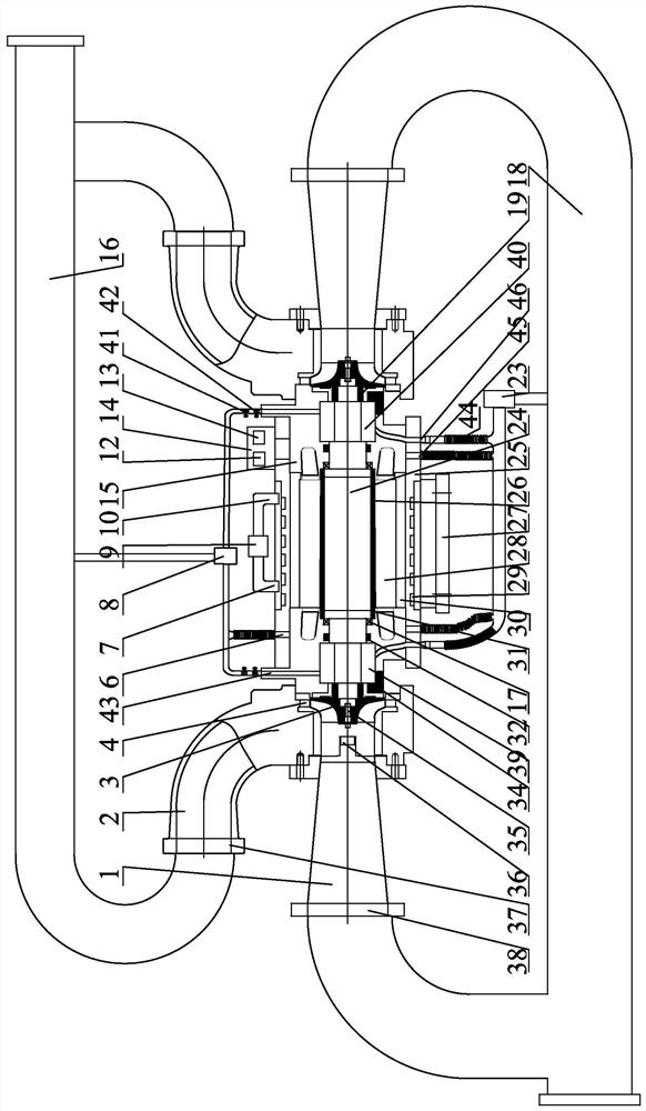
[0002] Turbine generators are widely used in the field of low-grade thermal energy utilization power generation technology. For ocean temperature difference power generation, based on the principle of organic Rankine cycle power generation, the characteristics of low-boiling organic working fluid are used to make the liquid working medium in the evaporator by The surface temperature seawater is heated and turned into steam, which then drives the turbine to do work and drives the generator to generate electricity. After being condensed by the deep seawater in the condenser, it becomes a liquid working medium, which is pumped back to the evaporator to continue working, forming a cycle. However, for low-grade thermal power generation such as ocean thermal energy, the radial turbine usually adopts a single turbine structure, and the generator is driven to generate electricity through a coupling. Not only is the power generation efficiency low, but the structure is large and not compact, which greatly increases Manufacturing cost. In order to improve the power generation efficiency of the turbine and improve the axial force and manufacturing cost of the single turbine structure, this patent uses a double-turbine direct-drive permanent magnet synchronous generator set. The turbines are arranged symmetrically and the axial The force offset not only solves the problem of axial force, but also solves the problem of high sealing performance due to the existence of axial force, and also improves the power generation efficiency. At the same time, the use of direct drive permanent magnet synchronous generator also makes the structure of the unit Compact, reduces manufacturing cost

Method used


Image

  • Double-turbine direct-driven permanent magnet synchronous generator set
  • Double-turbine direct-driven permanent magnet synchronous generator set

Examples


Embodiment 1

[0058] Such as figure 1 As shown, a magnetic levitation double-turbine direct-drive permanent magnet synchronous generator set includes a permanent magnet synchronous generator and two centripetal turbines located at both ends of the permanent magnet synchronous generator; the generator of the permanent magnet synchronous generator A cooling system is provided on the casing 25; the cooling system includes a cold water system arranged outside the generator casing and a cold air system communicated with the inside of the casing. The rotating shaft of the permanent magnet synchronous generator is in drive connection with the generator casing through the first magnetic suspension bearing 33 , the second magnetic suspension bearing 20 and the auxiliary bearing 17 via the bearing support 34 . The unit is mainly supported by the auxiliary bearing 17 during the start-up operation stage. The permanent magnet synchronous generator includes a generator winding stator core 28 , a rotor c...

Embodiment 2

[0071] Such as figure 2 As shown, an air-suspended twin-turbine direct-drive permanent magnet synchronous generator set includes a permanent magnet synchronous generator and two centripetal turbines located at both ends of the permanent magnet synchronous generator; A cooling system is provided on the casing 25; the cooling system includes a cooling water system arranged outside the generator casing and a cooling system connected to the inside of the casing; the cooling system is also used to supply air to the air bearing. The rotating shaft of the permanent magnet synchronous generator is connected to the generator casing through the first air bearing 39, the second air bearing, the auxiliary bearing 40 and the auxiliary bearing 17 through the bearing support 34; the air bearing is embedded in the bearing support Inside the seat 34. The auxiliary bearing is a tapered roller bearing, and the auxiliary bearing can bear axial load and radial load at the same time, and can bear...


PUM


Abstract

The invention relates to the technical field of centripetal turbine low-grade heat energy power generation, in particular to a double-turbine direct-driven permanent magnet synchronous generator set. The double-turbine direct-driven permanent magnet synchronous generator set comprises a permanent magnet synchronous generator, a control system and centripetal turbines, wherein a cooling system is arranged on a shell of the permanent magnet synchronous generator; the cooling system comprises a cold water system arranged on the outer side of the shell and a cold air system communicating with the interior of the shell; the control system is used for controlling the displacement state of a rotating shaft of the permanent magnet synchronous generator; the two centripetal turbines are symmetrically arranged at the two ends of the permanent magnet synchronous generator; and a first communicating pipe is connected to an inlet of each centripetal turbine, and a second communicating pipe is connected to an outlet of each centripetal turbine. The double-turbine direct-driven permanent magnet synchronous generator set can effectively offset axial force borne by the generator set, the generator set is free of friction loss and high in motion precision in the operation process, the size of the generator set can be reduced by adopting a direct drive mode, cost is saved, and power generation efficiency is improved.

Description

technical field [0001] The invention relates to the technical field of centripetal turbine low-grade thermal ocean temperature difference energy power generation, in particular to a twin-turbine direct-drive permanent magnet synchronous generator set. Background technique [0002] Turbine generators are widely used in the field of low-grade thermal energy utilization power generation technology. For ocean temperature difference power generation, based on the principle of organic Rankine cycle power generation, the characteristics of low-boiling organic working fluid are used to make the liquid working medium in the evaporator by The surface temperature seawater is heated and turned into steam, which then drives the turbine to do work and drives the generator to generate electricity. After being condensed by the deep seawater in the condenser, it becomes a liquid working medium, which is pumped back to the evaporator to continue working, forming a cycle. However, for low-grad...

Claims


Application Information

Patent Timeline
IPC IPC(8): F03G7/05F01D15/10F01D13/00F01D21/00F01D25/16H02K7/09H02K9/19H02K9/04H02K5/20
CPCF03G7/05F01D15/10F01D13/00F01D21/003F01D25/16H02K7/09H02K9/19H02K9/04H02K5/203H02K5/207Y02E10/30
Inventor 刘延俊陈云杨维杨晓玮薛钢史振宇王继来张成鹏
Owner SHANDONG UNIV
Learn More