Carrier for chemical polishing

A technology of chemical polishing and carrier, which is applied in the field of chemical polishing carrier, and can solve problems such as marks, poor circulation of solutions, and poor appearance of products

Active Publication Date: 2021-09-10
LENS TECH
View PDF6 Cites 0 Cited by
  • Summary
  • Abstract
  • Description
  • Claims
  • Application Information

AI Technical Summary

Problems solved by technology

[0004] However, when the traditional turnover carrier is used to carry the product to carry out chemical polishing on the product, because the solution in the chemical polishing pool flows very slowly, the solution flow is not smooth at the contact between the limit rack and the support rack and the product, especially At the point where the supporting racks are in contact with the product, due to the product being affected by its own gravity, the straight edge of the bottom of the product completely falls into the bottom of the V-shaped limit groove on the two supporting racks, so that the vertical position of the bottom of the product is consistent with the vertical position of the product. The front and back sides near the body position are in close contact with the support rack respectively. After the product falls into the V-shaped limit groove on the support rack, it is equivalent to fixing the product. Therefore, there is a phenomenon of solution retention, which prevents the solution from being replaced circularly. , the retained solution produces an irreversible chemical reaction with the supporting rack, causing marks on the product and making the product look bad

Method used


Image

  • Carrier for chemical polishing
  • Carrier for chemical polishing
  • Carrier for chemical polishing

Examples


Embodiment Construction

[0036] The following will clearly and completely describe the technical solutions in the embodiments of the present invention with reference to the accompanying drawings in the embodiments of the present invention. Obviously, the described embodiments are only some, not all, embodiments of the present invention. Based on the embodiments of the present invention, all other embodiments obtained by persons of ordinary skill in the art without making creative efforts belong to the protection scope of the present invention.

[0037] The core of the present invention is to provide a carrier for chemical polishing, which can reduce the mark on the bottom of the product and improve the appearance yield of the product.

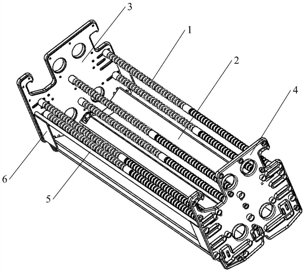
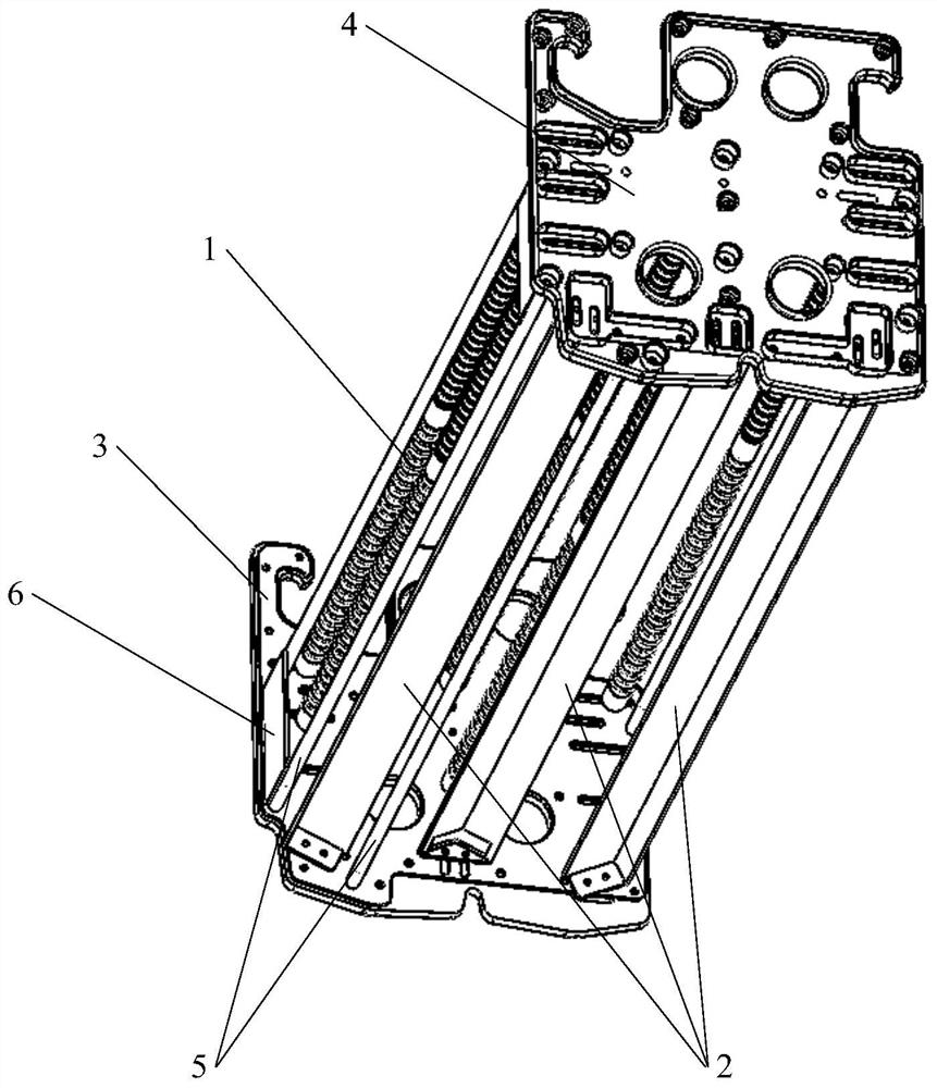
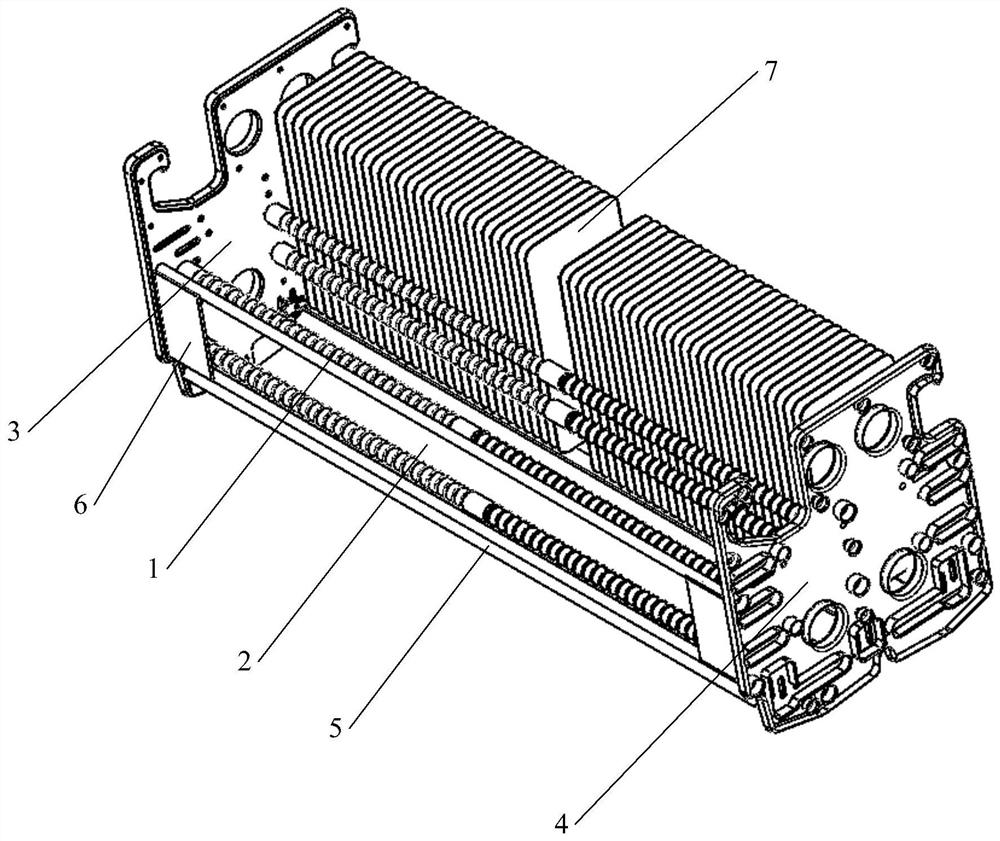
[0038] Please refer to Figure 1-Figure 12 , is the accompanying drawing of the description of the present invention.

[0039] The present invention provides a carrier for chemical polishing, which includes at least one limit support assembly, each limit support assem...


PUM


Abstract

The invention discloses a carrier for chemical polishing. The carrier comprises at least one limiting and supporting assembly; each limiting and supporting assembly comprises two sets of limiting racks arranged at intervals and two slope surfaces located below the two sets of limiting racks correspondingly; each limiting rack is correspondingly provided with a plurality of V-shaped grooves; the two slope surfaces incline in the directions away from each other. According to the carrier for chemical polishing, the supporting mode of the bottom of a product is changed, namely, the contact mode of the bottom of the product and the carrier is changed. The two slope surfaces are adopted to support two round corners at the bottom of the product respectively, so that the round corners of the product make point-surface contact with the slope surfaces, the contact area between the bottom of the product and the carrier is greatly reduced, the flowing smoothness of a solution in a chemical polishing pool in the contact positions of the round corners of the product and the slope surfaces can be ensured, solution retention is prevented, and the phenomenon that the appearance of the product is poor due to the fact that the product is imprinted due to chemical reaction between the retained solution and the slope surfaces is avoided.

Description

technical field [0001] The invention relates to the technical field of chemical polishing process equipment, more specifically, to a carrier for chemical polishing. Background technique [0002] For electronic product components such as front and rear covers of mobile phones, watches, car displays, computer displays, and camera lenses, chemical polishing is usually involved. The process is to put the product into a chemical polishing pool for chemical polishing to remove the internal Dark spots and micro-cracks on the surface, and enhance the product's plane strength and four-sided compression resistance. [0003] At present, when products are put into the chemical polishing pool, the traditional turnover carrier is used to carry the product, that is, the product is put into the turnover carrier, and then the turnover carrier is put into the chemical polishing pool as a whole. The traditional carrier in the prior art includes four limit racks and two support racks, and the ...

Claims


Application Information

Patent Timeline
IPC IPC(8): C23F3/00
CPCC23F3/00
Inventor 张灿
Owner LENS TECH
Why Eureka
Try Eureka