Flat yarn warping machine

A warping machine and flat wire technology, applied in the field of warping machines, can solve the problems of flat wire failure, unstable cylinder drive, affecting warping quality, etc., to avoid deformation or damage, overcome pressure instability, and ensure warping. quality effect

Active Publication Date: 2016-11-30
NEWTRY COMPOSITE
View PDF8 Cites 0 Cited by
  • Summary
  • Abstract
  • Description
  • Claims
  • Application Information

AI Technical Summary

Problems solved by technology

The warping machines in the prior art are generally used for warping ordinary yarns (yarns with a circular cross section). After the yarn comes out of the creel, it passes through the tension control system, and the yarn is directly guided by the pressure roller. It enters the winding of the flat yarn, but due to the special structure of the flat yarn itself, the flat yarn cannot be twisted or deformed during the warping process. There is a certain gap between them. When the flat yarn is directly guided by the pressure roller and enters the pan head, it may fall into the gap between the pressure roller and the pan head from the edge of the pressure roller, and the warping quality of the edge of the pressure roller cannot be guaranteed. Some people may propose to set ribs on the edge of the pressure roller to prevent the flat yarn from slipping, but this shortens the width of the warping machine and affects the number of ends of the warped flat yarn. If the requirements of warp knitting are met, the width of the pressure roller will inevitably be increased, so the volume of the warping machine will inevitably increase, resulting in an increase in the cost of the warping machine
[0004] In the existing pressure roller adjustment mechanism, the pressure roller is driven by the air cylinder to cover the surface of the pan head, but the air cylinder is driven by air. Due to the compressibility of the air, the cylinder drive is not stable. When the pressure of the roller is too high, the air in the cylinder will be compressed, resulting in uneven pressure of the pressure roller, which may cause unevenness on the surface of the warping machine, affecting the quality of warping
[0005] Furthermore, the traction roller in the prior art is a roller body with a smooth surface. When the flat yarn contacts the surface of the roller body of the traction roller, there is an arc surface contact between the flat yarn and the traction roller. During the process, the flat yarn may be overturned to form a twist. In the prior art, in order to avoid the flat yarn from twisting on the traction roller, it is prevented by increasing the tension of the flat yarn, but increasing the tension of the flat yarn will bring The biggest problem is that it is easy to break the wire, and the above problems have affected the warping quality of the flat wire

Method used


Image

  • Flat yarn warping machine
  • Flat yarn warping machine
  • Flat yarn warping machine

Examples


Embodiment Construction

[0037] The present invention will be further described below in conjunction with the accompanying drawings.

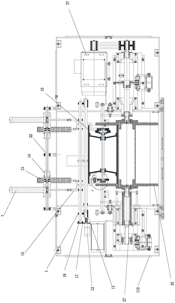
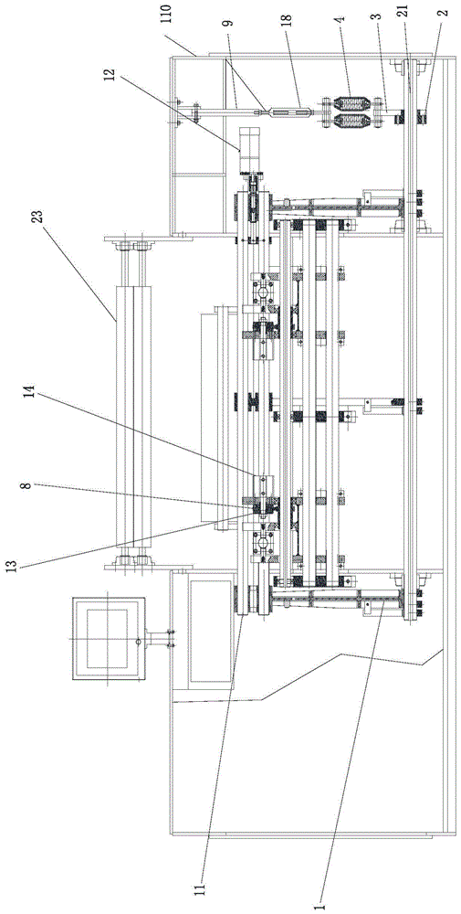
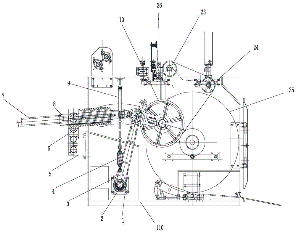
[0038] like Figure 1 to Figure 3 Shown flat wire warping machine, it comprises frame 110, and the middle part of frame 110 is provided with warp head 25, and frame 110 is provided with the automatic clamping mechanism that clamps and fixes the head, clamping The mechanism is convenient for the loading and unloading of the warping head, and the pressure roller for pressing the warping head is arranged on the left side of the warping head, and the drive motor 27 for driving the rotation of the warping head is arranged on the frame. The drive motor 27 drives the warping head 25 through a belt, and the frame 110 has a pressure roller adjustment mechanism for adjusting the position of the pressure roller and the pressure of the pressure roller, and also includes a group of side yarn devices 24 arranged on the frame 110 , the side yarn device 24 is positioned above the war...


PUM


Abstract

A flat yarn warping machine comprises a stander (110) having a compression roller adjusting mechanism for adjusting both the position and the pressure of a compression roller (10), the flat yarn warping machine further comprises a group of edge yarn devices (24) arranged on the stander (110), and the edge yarn devices (24) are positioned above a warp beam flange (25) and above the end part of the compression roller (10). The edge yarn devices (24) comprise a mounting shaft (2441) fixed on the stander (110). An edge thread roller (2448) is provided on the mounting shaft (2441) positioned at one side of the stander (110). A roller mounting plate (2447) is provided on the mounting shaft (2441) positioned at one side of the edge thread roller (2448). A sliding shaft (2446) is provided on the roller mounting plate (2447). The other end of the sliding shaft (2446) is fixedly provided with a baffle plate (2443). A threaded shaft (2444) is arranged between the baffle plate (2443) and the roller mounting plate (2447). A sliding seat (2445) for guiding a flat yarn is arranged on the threaded shaft (2444), and the slide seat (2445) is also sleeved on the slide shaft (2446). An adjusting hand wheel (2442) is provided on the end part of the threaded shaft (2444). The flat yarn warping machine can keep the flat yarn from falling into the gap between the end part of the compression roller (10) and the warp beam flange (25), and thereby solving the problem of less uniformity of the warp beam flange surface.

Description

technical field [0001] The invention relates to the field of warping machines, in particular to a flat wire warping machine used for flat wire warping. Background technique [0002] The flat wire warping machine is used for warping flat wires. In the warping process, in order to ensure the warping quality of the flat yarn on the pan head, the pressure roller is required to cover the flat yarn on the surface of the pan head to prevent the surface of the pan head from being uneven and the thickness of the pan head uneven during the warping process The problem. [0003] The flat yarn in the present invention is a wire with a width of 2.5 mm. The warping machines in the prior art are generally used for warping ordinary yarns (yarns with a circular cross section). After the yarn comes out of the creel, it passes through the tension control system, and the yarn is directly guided by the pressure roller. It enters the winding of the flat yarn, but due to the special structure of...

Claims


Application Information

Patent Timeline
Patent Type & Authority Patents(China)
IPC IPC(8): D02H13/00D02H3/00
CPCD02H3/00D02H13/00
Inventor 谈灵芝陈亚飞谢雪松陈龙
Owner NEWTRY COMPOSITE
Why Eureka
Try Eureka