Cutting machining forming method for L-shaped thin-wall ring piece

A technology of cutting processing and forming method, applied in the field of cutting processing technology, can solve the problems of poor rigidity of the workpiece, affecting processing accuracy and processing quality, and less cutting amount

Inactive Publication Date: 2021-09-10
GUIZHOU LIYANG INT MFG
View PDF11 Cites 0 Cited by
  • Summary
  • Abstract
  • Description
  • Claims
  • Application Information

AI Technical Summary

Problems solved by technology

[0002] In the cutting process, when the workpiece has multiple surfaces to be processed, the existing technology usually cuts one of the surfaces to be processed first, and then transforms the posture of the workpiece, using the processed surface as a positioning reference for the rest However, in the process of cutting thin-walled ring parts, due to the thin wall and poor rigidity of the workpiece, the workpiece is prone to cutting vibration or deformation under the cutting force of the cutting tool, which affects the forming quality of the workpiece and machining accuracy. In addition, in the process of cutting one of the workpiece surfaces to be processed, it is also eas...

Method used


Image

  • Cutting machining forming method for L-shaped thin-wall ring piece
  • Cutting machining forming method for L-shaped thin-wall ring piece
  • Cutting machining forming method for L-shaped thin-wall ring piece

Examples


Embodiment Construction

[0027] The technical solution of the present invention is further described below, but the scope of protection is not limited to the description.

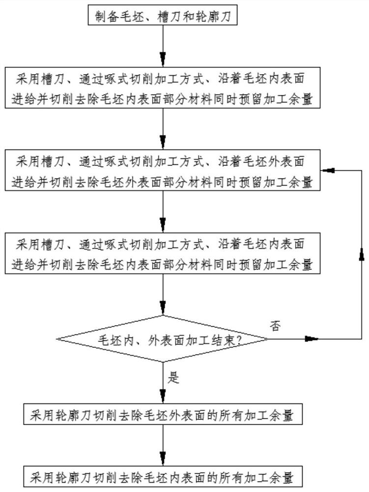
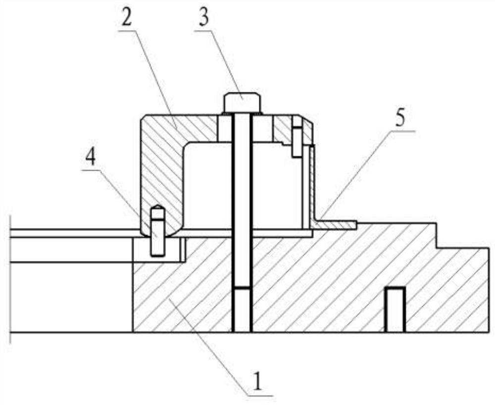
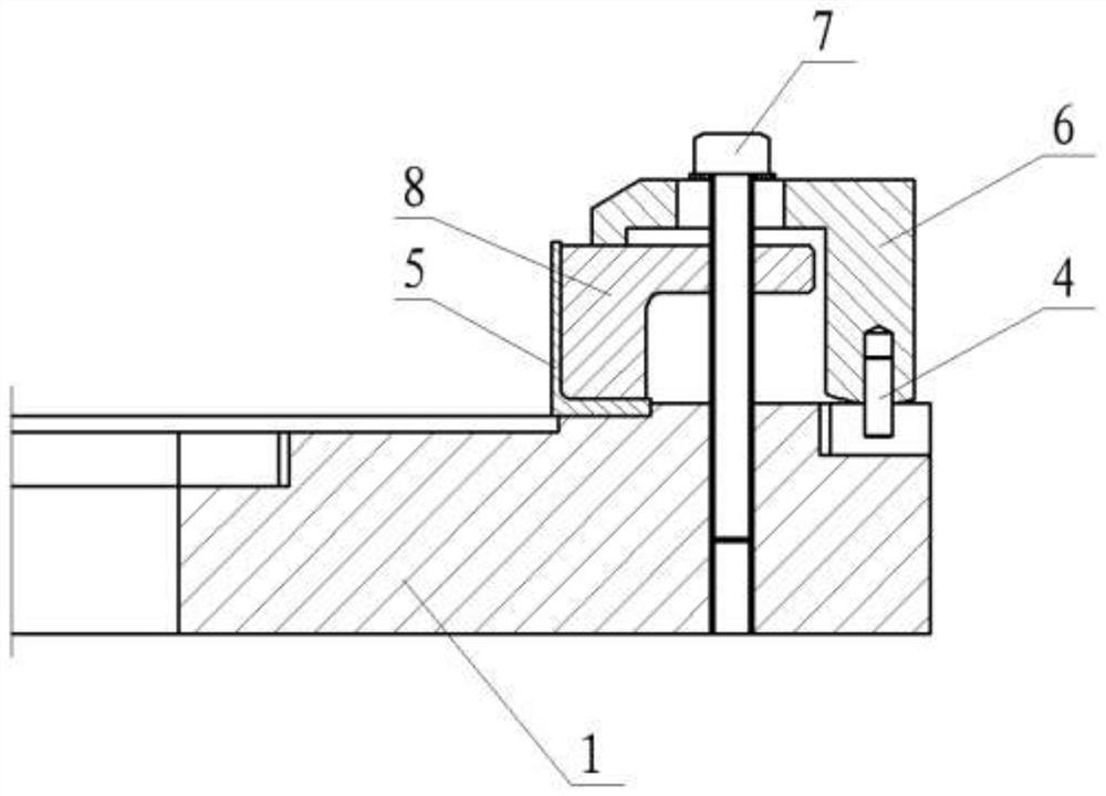
[0028] Such as figure 1 , figure 2 and image 3 As shown, the present invention provides a method for cutting and forming L-shaped thin-walled rings, comprising the following steps:

[0029] Step 1: Prepare the blank 5, the groove knife and the profile knife; further, the material of the groove knife is cemented carbide. The material of the contour knife is carbide. The overall shape of the contour knife is rhombus. Contour tools are turning tools.

[0030] Step 2: Using the groove cutter in step 1, feeding along the inner surface of the blank 5 and cutting and removing part of the material on the inner surface of the blank 5 through the pecking cutting processing method, and reserving an appropriate machining allowance;

[0031] Step 3: Using the groove cutter in step 1, feeding along the outer surface of the blank 5 and cu...


PUM


Abstract

The invention provides a cutting machining forming method for an L-shaped thin-wall ring piece. The cutting machining forming method comprises the following steps of preparing a blank, a groove cutter and a contour cutter; feeding along the inner surface of the blank by adopting the groove cutter, cutting to remove partial material on the inner surface of the blank and reserving machining allowance; feeding along the outer surface of the blank by adopting the groove cutter, cutting to remove partial material on the outer surface of the blank and reserving machining allowance; feeding along the inner surface of the blank by adopting the groove cutter, cutting to remove partial material on the inner surface of the blank and reserving machining allowance; repeating the steps for a plurality of times; cutting and removing all machining allowances on the outer surface of the blank by adopting the contour cutter; and cutting and removing all machining allowances on the inner surface of the blank by adopting the contour cutter. According to the technical scheme, the inner surface and the outer surface of the blank are cut in a staggered alternating mode, the feeding direction of a cutter is corrected, the rigidity of a workpiece is improved, deformation of the workpiece is reduced, over-cutting phenomenon during machining is avoided, and machining precision and machining quality are improved.

Description

technical field [0001] The invention belongs to the technical field of cutting processing technology, and in particular relates to a cutting processing forming method of an L-shaped thin-walled ring. Background technique [0002] In the cutting process, when the workpiece has multiple surfaces to be processed, the existing technology usually cuts one of the surfaces to be processed first, and then transforms the posture of the workpiece, using the processed surface as a positioning reference for the rest However, in the process of cutting thin-walled ring parts, due to the thin wall and poor rigidity of the workpiece, the workpiece is prone to cutting vibration or deformation under the cutting force of the cutting tool, which affects the forming quality of the workpiece and machining accuracy. In addition, in the process of cutting one of the workpiece surfaces to be processed, it is also easy to appear uneven thickness of the formed workpiece wall thickness. This is because...

Claims


Application Information

Patent Timeline
IPC IPC(8): B23P15/00
CPCB23P15/00
Inventor 严萍张江峰李井平李飞扬
Owner GUIZHOU LIYANG INT MFG
Why Eureka
Try Eureka