
LED lamp circuit board welding process applying LLC series resonance circuit

A series resonant circuit, LED lamp technology, applied in the direction of assembling printed circuits with electrical components, printed circuits, printed circuit manufacturing, etc., can solve the problem of difficult collection of insulating layers, etc.

Inactive Publication Date: 2021-09-07
浙江凯友照明科技有限公司
View PDF1 Cites 0 Cited by
  • Summary
  • Abstract
  • Description
  • Claims
  • Application Information

AI Technical Summary

Problems solved by technology

[0005] In view of the above problems, one of the purposes of the present invention is to address the deficiencies of the prior art and provide a circuit board welding process for LED lamps using an LLC series resonant circuit. Solder paste and guide the collection of the insulating layer, which solves the technical problem that the insulating layer is difficult to collect in the prior art

Method used


Image

  • LED lamp circuit board welding process applying LLC series resonance circuit
  • LED lamp circuit board welding process applying LLC series resonance circuit
  • LED lamp circuit board welding process applying LLC series resonance circuit

Examples


Embodiment 1

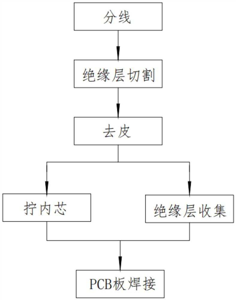
[0061] Such as figure 1 As shown, a circuit board welding process for LED lights using an LLC series resonant circuit includes the following steps:

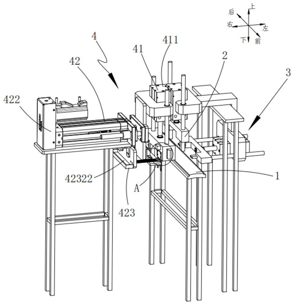
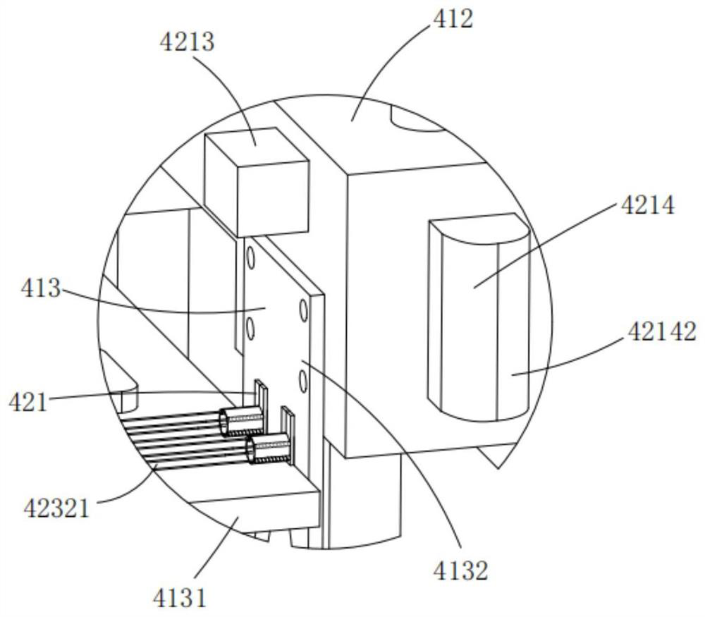
[0062] Step 1: Wire splitting, the wire feeding device 3 is sent to cooperate with the wire block mechanism 413, and the wire driving mechanism 411 drives the wire block mechanism 413 to move down to separate the wires separately;

[0063] Step 2: cutting the insulation layer. After step 1, the power assembly 422 drives the wire block mechanism 413 to move laterally, and then straightens the wire, and then the cutting assembly 421 cuts the insulation layer of the wire. At the same time, several groups of round rollers 4216 will The cut insulation is fixed;

[0064] Step 3: peeling, after step 2, the power assembly 422 continues to drive the wire block mechanism 413 to move laterally, the cutting assembly 421 removes the insulating layer, and at the same time, the smearing unit 4214 applies solder paste to the inner core of the w...

Embodiment 2

[0077] Such as figure 2 As shown, a circuit board welding process for LED lamps using an LLC series resonant circuit, including conveying equipment for conveying PCB boards, welding equipment arranged directly above the conveying equipment, and located on the left and right sides of the conveying equipment Wire feeding equipment and wire stripping equipment, the wire stripping equipment includes:

[0078] A wire distribution device, the wire distribution device can be moved up and down, the wire distribution device is provided with an accommodation chamber, and the accommodation chamber separates the wires separately;

[0079] A peeling device, the peeling device includes a cutting assembly located around the accommodating cavity and used to cut the wire insulation, a power assembly that drives the cutting assembly to move laterally to remove the insulation sheet, and drives the insulation to move A control assembly that rotates in the center and collects loose insulation. ...


PUM


Abstract

The invention provides an LED lamp circuit board welding process applying an LLC series resonance circuit. The process comprises the following steps: branching: a wire feeding device feeds wires to be matched with a wire guide block mechanism, and a wire guide driving mechanism drives the wire guide block mechanism to move downwards to separate wires independently; insulating layer cutting: the power assembly drives the wire guide block mechanism to transversely move so as to straighten the wire, and then the cutting assembly cuts the insulating layer of the wire; peeling: the power assembly continuously drives the wire block mechanism to transversely move, the cutting assembly takes off the insulating layer, and meanwhile, the coating unit coats the inner core of the electric wire with soldering paste; screwing of the inner core: driving a plurality of groups of round rollers to rotate synchronously by the control assembly so as to tighten the inner core; insulating layer collection: the round roller drives the insulating layer to rotate and drives the insulating layer to move in the axial direction for collection at the same time; PCB welding: the wire feeding device moves back and conveys the electric wire to be matched with the PCB on the conveying device, and finally welding is conducted through the welding device. According to the invention, the insulating layer can be collected while the welding efficiency is improved.

Description

technical field [0001] The invention relates to the technical field of LED lamp processing, in particular to a circuit board welding process for LED lamps using an LLC series resonant circuit. Background technique [0002] The LED lamp using the LLC series resonant circuit has low loss and high efficiency. In the existing LED lamp, the LLC series resonant circuit board is directly connected in the housing of the LED lamp through fasteners, and the LLC series resonant circuit board provides power for the LED lamp. , so the power line needs to be welded on the circuit board, and the existing welding methods are mostly manual welding, and the labor cost is high. [0003] The invention patent with the Chinese patent application number CN201610291613.4 discloses a highly stable wire cutting and stripping device and an automatic welding machine. The wire cutting and stripping device includes a support plate, a cutting and stripping knife mold, a knife mold fixing seat and a drivi...

Claims


Application Information

Patent Timeline
Patent Type & Authority Applications(China)
IPC IPC(8): H05K13/04H05K3/34
CPCH05K3/341H05K13/0465
Inventor 沈彩靖姜如友姜如银
Owner 浙江凯友照明科技有限公司
Learn More