
Voltage-sharing element applied to power equipment and design method of voltage-sharing element

A technology of power equipment and components, applied in the field of voltage equalizing components and its design, can solve the problems of high R&D cost and long R&D cycle

Pending Publication Date: 2021-09-07
XIAN SHENDIAN ELECTRONICS +1
View PDF0 Cites 0 Cited by
  • Summary
  • Abstract
  • Description
  • Claims
  • Application Information

AI Technical Summary

Problems solved by technology

[0005] In order to overcome the problems of high R&D cost and long R&D period caused by the current structure of the voltage equalizing element and the size matching with the power equipment, the present invention provides a voltage equalizing element applied to the power equipment and its design method

Method used


Image

  • Voltage-sharing element applied to power equipment and design method of voltage-sharing element
  • Voltage-sharing element applied to power equipment and design method of voltage-sharing element
  • Voltage-sharing element applied to power equipment and design method of voltage-sharing element

Examples


Embodiment 1

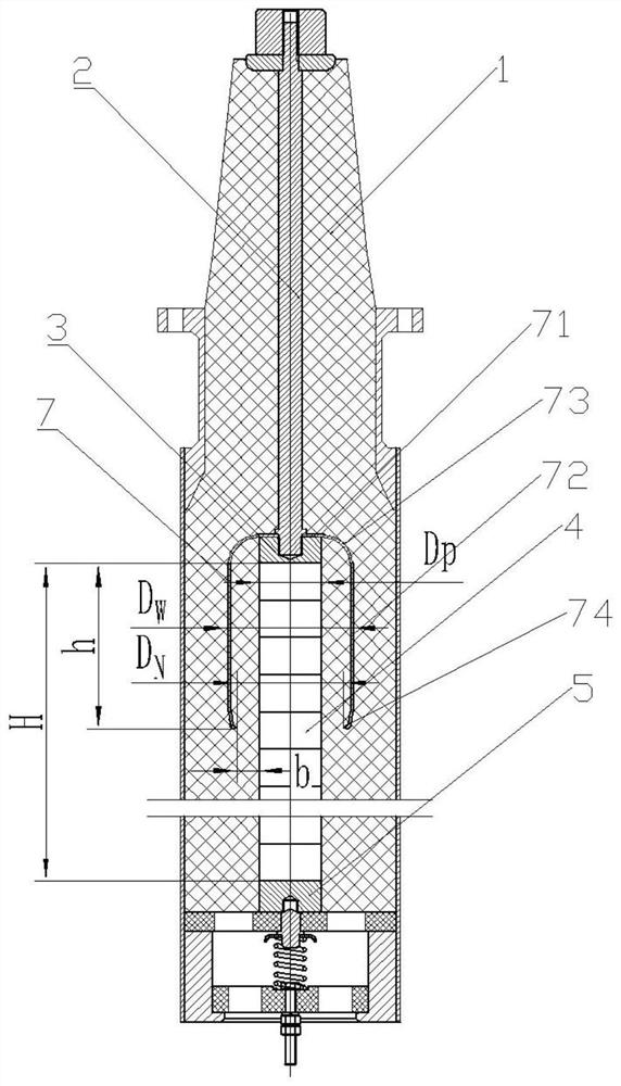
[0102] Such as figure 1 As shown, the electrical equipment in this embodiment is a shielded plug-in lightning arrester, including an insulating layer 1, a first conductor 2, a second conductor 3, a valve body 4 and a first conductor located in the insulating layer 1 and arranged in sequence according to the current transmission direction. three conductors 5;

[0103] The pressure equalizing element 7 is made of conductive or semi-conductive material, including the bottom of the barrel and the barrel body; the bottom of the barrel is a first disc 71 with fixing holes, the barrel body is a thin-walled cylindrical structure 72, and the bottom of the first disc 71 The surface is electrically connected to the upper surface of the second conductor 3, the upper end of the thin-walled cylindrical structure 72 is connected to the edge of the first disc 71 through a circular arc transition section 73, and the other end extends toward the direction of the third conductor 5, and the thin-...

Embodiment 2

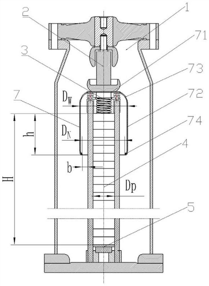
[0148] Such as figure 2 As shown, the power equipment in this embodiment is a GIS arrester, including an insulating layer 1, a first conductor 2, a second conductor 3, a valve body 4 and a third conductor 5 located in the insulating layer 1 and arranged in sequence according to the current transmission direction ; The difference from Example 1 is that the insulating layer 1 of the arrester is made of SF6 gas.

[0149] The pressure equalizing element 7 is made of conductive or semi-conductive materials, including the bottom of the barrel and the barrel; the bottom of the barrel is a first disc 71, and the barrel is a thin-walled cylindrical structure 72. The lower surface of the first disc 71 is connected to the second conductor. The upper surface of the thin-walled cylindrical structure 72 is electrically connected to the upper surface of the thin-walled cylindrical structure 72. The upper end of the thin-walled cylindrical structure 72 is connected to the edge of the first d...

Embodiment 3

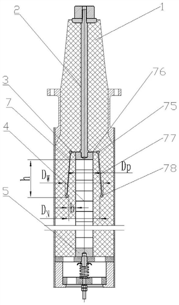
[0194] Such as image 3 As shown, the electric equipment in this embodiment is the same as that in Embodiment 1, and it is also a shielded plug-in lightning arrester, including an insulating layer 1, a first conductor 2 and a second conductor located in the insulating layer 1 and arranged in sequence according to the current transmission direction 3. The valve body 4 and the third conductor 5;

[0195] The pressure equalizing element 7 is made of conductive or semi-conductive material, including the bottom of the barrel and the barrel body; the bottom of the barrel includes a first ring 75 and a second disc 76, the second disc 76 is sleeved outside the first conductor 2, and the second The lower surface of the second disk 76 is electrically connected to the upper surface of the second conductor 3, and the outer edge of the second disk 76 is provided with the first ring 75; the barrel includes some connecting ribs 77 and the second ring 78; The circular ring 78 is arranged par...


PUM


Abstract

The invention belongs to the field of overvoltage protection, and particularly relates to a voltage-sharing element applied to power equipment and a design method of the voltage-sharing element. The problems of high research and development cost, long research and development period and the like caused by the fact that the structure of the current voltage-sharing element and the size matching of the current voltage-sharing element and power equipment are determined only by experience are solved. The voltage-sharing element comprises a barrel bottom and a barrel body; the barrel bottom is used for being electrically connected with a second conductor in the electrical equipment, the upper end of the barrel body is connected with the edge of the barrel bottom, the lower end of the barrel body extends towards a third conductor of an electrified part, and a radial gap is formed between the barrel body and part of the valve body close to the second conductor and is filled with an insulating medium; therefore, aging speed acceleration caused by serious heating in the operation process of the power equipment is prevented, and the operation safety and the protection reliability of the power equipment are greatly improved; meanwhile, by optimizing the effective height of the voltage-sharing element and the radial gap between the voltage-sharing element and the valve body, the discharge phenomenon between the valve body and the voltage-sharing element is avoided, and the protection reliability of the power equipment is further improved.

Description

technical field [0001] The invention belongs to the field of overvoltage protection, and in particular relates to a voltage equalizing element applied to power equipment and a design method thereof. Background technique [0002] When the existing shielded plug-in arrester operates in a power system with a low voltage level (that is, the voltage is 35kV and below), the charging rate in actual operation is far lower than the designed charging rate. At the same time, due to the low height of the valve body, the arrester The problem of uneven potential distribution is not obvious. However, when the arrester is applied to a system with a higher voltage level (that is, the voltage is 66kV and above), the height of the valve body increases, and the charging rate of the arrester will greatly increase during the actual operation. , the stray capacitance between the internal valve body and the shielding shell increases, which further increases the uneven potential distribution of the...

Claims


Application Information

Patent Timeline
Patent Type & Authority Applications(China)
IPC IPC(8): H02H9/04G01R19/165G01R1/04G01R1/18
CPCH02H9/04G01R19/165G01R1/0408G01R1/18
Inventor 叶德平马向荣
Owner XIAN SHENDIAN ELECTRONICS
Learn More