Computer optometry unit

A refractometer and computer technology, applied in the field of computer refractor, can solve the problems of difficulty in achieving high precision and high repeatability, insufficient accuracy and thoroughness of human eye inspection, affecting the accuracy of measurement data, etc., so as to avoid subjective deviation and ensure accurate and thorough inspection. , the effect of high precision and high repeatability measurement

Pending Publication Date: 2021-09-03
NINGBO MING SING OPTICAL R & D
View PDF11 Cites 0 Cited by
  • Summary
  • Abstract
  • Description
  • Claims
  • Application Information

AI Technical Summary

Problems solved by technology

However, this method is susceptible to the subjective influence of optometrists, and it is difficult to achieve high precision and high repeatability, which will eventually affect the accuracy of measurement data
In addition, most of the current computer refractometers can only calculate the low-order aberrations of the human eye. The low-order aberrations are common refractive errors such as myopia, hyperopia, and regular astigmatism. Aberrations (higher-order aberrations are caused by irregular astigmatism, spherical aberration, coma, etc.) but powerless, resulting in inaccurate and thorough inspection of human eyes

Method used


Image

  • Computer optometry unit
  • Computer optometry unit
  • Computer optometry unit

Examples


Embodiment 1

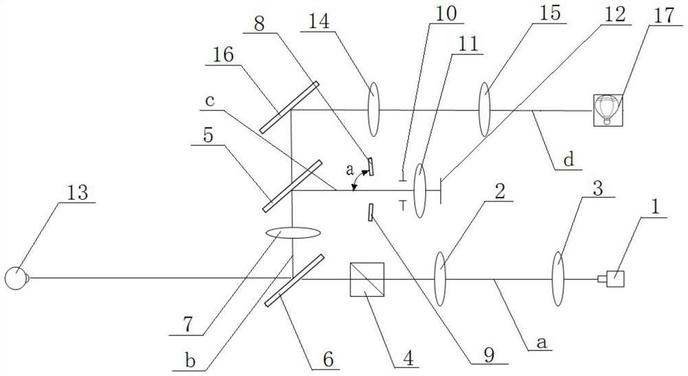
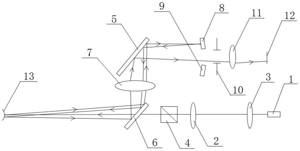
[0022] Embodiment 1: As shown in the figure, a computer optometry instrument includes a fog optical path and a focusing optical path. The focusing optical path includes a laser 1, a first light source lens 2, a second light source lens 3, a PBS (polarization beam splitter) 4, and a second light source lens. A beam splitter 5, a second beam splitter 6, an objective lens 7, a first focusing mirror 8, a second focusing mirror 9, a telecentric diaphragm 10, a corneal objective lens 11 and a first detector 12, a second beam splitting mirror 6, and a PBS 4 , the first light source lens 2, the second light source lens 3 and the laser 1 are located on the first optical axis a and arranged in sequence with the optical axis, the first light source lens 2 is a positive lens, and the second beam splitter 6 is located on the side close to the eyeball 13 , the second beamsplitter 6 is located on the second optical axis b with the objective lens 7 and the first beamsplitter 5 and is arranged ...

Embodiment 2

[0026] Embodiment 2: As shown in the figure, on the basis of Embodiment 1, the computer refractometer is provided with an aberration analysis optical path that can be used to analyze high and low price aberrations of the human eye. The aberration analysis optical path includes the second Detector 18, microlens array 19, first lens 20, second lens 21, first relay lens 22, second relay lens 23 and second mirror 24, first lens 20, second lens 21 and the first The two relay lenses 23 are all positive lenses, the second mirror 24, the first lens 20 and the PBS 4 are located on the fifth optical axis e and are arranged in sequence with the optical axis, and the second mirror 24 is connected with the first relay lens 22 at the same time. , the second relay lens 23, the second lens 21, the microlens array 19, and the second detector 18 are located on the sixth optical axis f and are arranged in sequence with the optical axis, and the second mirror 24 is used to pass through the first l...


PUM

PropertyMeasurementUnit
angleaaaaaaaaaa

Abstract

The invention discloses a computer optometry unit. The computer optometry unit comprises a fogging light path and a focusing light path, and is characterized in that the focusing light path comprises a laser, a first light source lens, a second light source lens, a PBS, a first spectroscope, a second spectroscope, an objective lens, a first focusing lens, a second focusing lens, a telecentric diaphragm, a cornea objective lens and a first detector. The second spectroscope, the PBS, the first light source lens, the second light source lens and the laser are located on a first optical axis and are sequentially arranged on the same optical axis, the first spectroscope, the objective lens and the second spectroscope are located on a second optical axis and are sequentially arranged on the same optical axis, and the first spectroscope, the telecentric diaphragm, the cornea objective lens and the first detector are located on a third optical axis and are sequentially arranged on the same optical axis. The first focusing lens and the second focusing lens are symmetrically arranged along the third optical axis and are located between the first spectroscope and the telecentric diaphragm. The unit has the advantages that whether the vertex of the cornea is focused or not is judged simply, visually and accurately, the focusing accuracy of the vertex of the cornea is improved, and high-precision and high-repeatability measurement of human eyes is realized.

Description

technical field [0001] The invention relates to optometry equipment for checking human eyes, in particular to a computer optometry instrument. Background technique [0002] There are mainly two kinds of optometry methods for human eyes, subjective optometry and objective optometry. Subjective optometry is an inspection method that relies on the subjective visual ability of the inspected to determine the nature and abnormality of the refractive state. The commonly used method is to put the lens in front of the patient for corrected visual acuity examination when the pupil is kept in a natural state (without dilating), and determine the nature of the refractive error and the appropriate corrective lens power according to the patient's subjective vision. Also known as the insert method or the obvious optometry method, but it has the problems of not being fully automatic and taking a long time to measure. The objective optometry method is to rely on optometrists or ophthalmolo...

Claims


Application Information

Patent Timeline
Patent Type & Authority Applications(China)
IPC IPC(8): A61B3/103
CPCA61B3/103
Inventor 沃圣杰马孟鸿骆晟俞斌毛维波
Owner NINGBO MING SING OPTICAL R & D
Why Eureka
Try Eureka