
Biomass fuel desulfurization and denitrification system

A biomass fuel, desulfurization and denitrification technology, applied in the field of biomass fuel desulfurization and denitrification system, can solve the problems of dry wall, affecting the effect of flue gas desulfurization and denitrification, uneven liquid distribution, etc.

Pending Publication Date: 2021-08-31
郭建成
View PDF10 Cites 0 Cited by
  • Summary
  • Abstract
  • Description
  • Claims
  • Application Information

AI Technical Summary

Problems solved by technology

[0004] In order to make up for the deficiencies of the prior art and solve the wall flow effect that is prone to occur when the packed tower is used in the prior art, the distribution of the liquid flowing down the packing surface is uneven or even dry wall phenomenon occurs, making the contact area of ​​the gas-liquid two phases The reduction of the Ach reaction time reduces the efficiency of mass transfer and separation, thereby affecting the desulfurization and denitrification effect of flue gas. The present invention proposes a desulfurization and denitrification system for biomass fuel

Method used


Image

  • Biomass fuel desulfurization and denitrification system
  • Biomass fuel desulfurization and denitrification system
  • Biomass fuel desulfurization and denitrification system

Examples


Embodiment approach

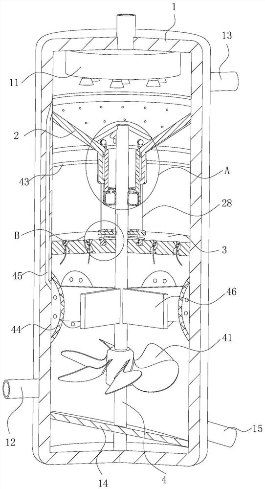
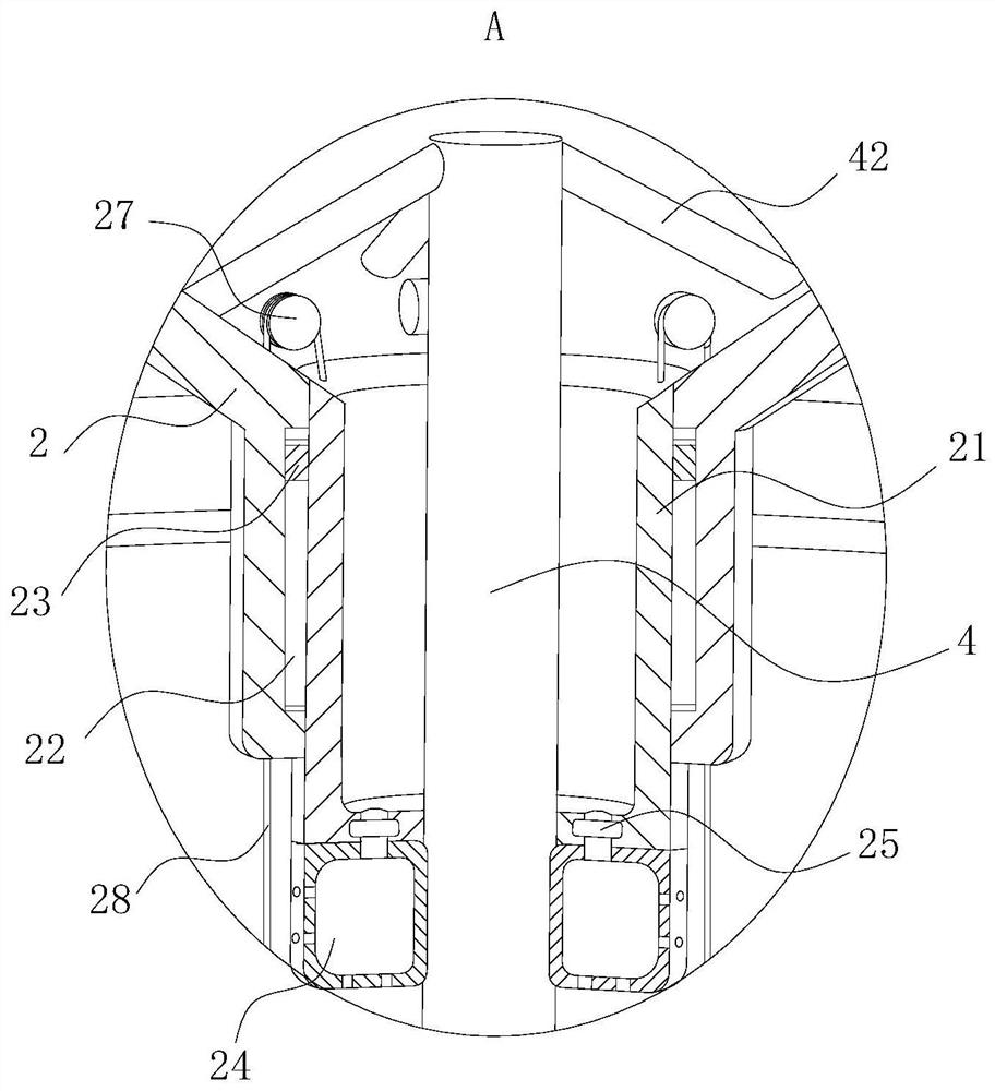
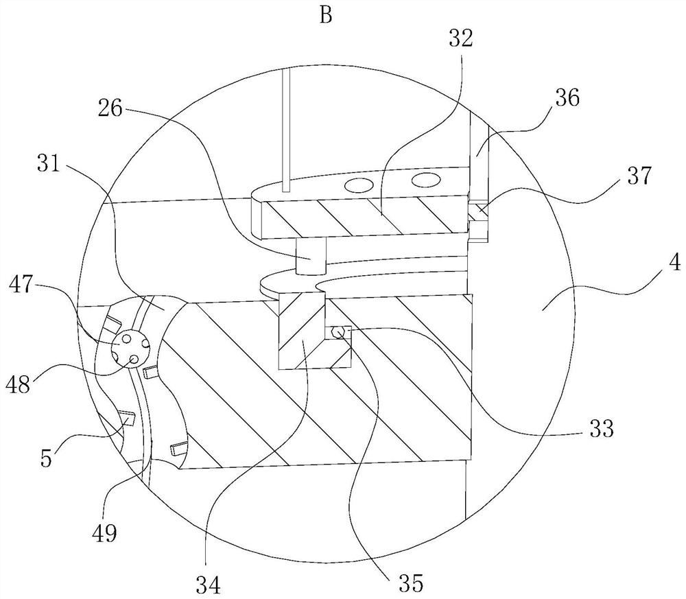
[0027] As an embodiment of the present invention, the middle part of the tower body 1 is rotatably connected with a rotating shaft 4, and the lower end of the rotating shaft 4 is provided with an impeller 41. The impeller 41 rotates; the second connecting rod 42 evenly distributed is fixedly connected between the upper end of the rotating shaft 4 and the inner wall of the guide cylinder 2, and the sliding cylinder 21 and the packing plate 3 are all connected to the rotating shaft 4 in rotation; the packing plate 3 The middle part of the upper surface is provided with an annular groove 33 with an "L"-shaped design in section, and a swivel 34 with an "L"-shaped design in the annular groove 33 is rotatably connected therein. Evenly arranged balls 35 are arranged between them, and the upper surface of the swivel 34 is fixedly connected with the extruding plate 32 through the evenly arranged first connecting rod 26; A second clamping block 37 is fixedly connected to the pressing pl...


PUM


Abstract

The invention belongs to the technical field of waste gas purification, and particularly relates to a biomass fuel desulfurization and denitrification system which comprises a tower body, a guide cylinder and a filler plate, a spraying box is arranged in the upper end of the tower body, the guide cylinder in a funnel-shaped design is arranged below the spraying box, and a sliding cylinder is arranged in the middle of the guide cylinder; first liquid bags which are uniformly distributed are arranged on the lower surface of the sliding cylinder; a filler plate is arranged below the guide cylinder; an extrusion plate is arranged between the filler plate and the liquid bags, and first connecting rods which are uniformly distributed are arranged between the extrusion plate and the filler plate; and fixed pulleys which are evenly distributed are arranged on the inner wall of the guide cylinder, pull ropes which are evenly distributed are fixedly connected to the upper surface of the sliding cylinder, and one ends of the pull ropes penetrate through the fixed pulleys and the side wall of the guide cylinder to be fixedly connected with the upper surface of an extrusion plate. An absorbent is collected, the wall flow effect is prevented, the absorbent is evenly dispersed on the filler plate, the gas-liquid contact area is increased, the gas-liquid contact time is prolonged, and the mass transfer separation efficiency and the flue gas desulfurization and denitrification effect are improved.

Description

technical field [0001] The invention belongs to the technical field of exhaust gas purification, in particular to a desulfurization and denitrification system for biomass fuel. Background technique [0002] Biomass fuel refers to the burning of biomass materials as fuel, generally mainly agricultural and forestry waste. The flue gas emitted after biomass fuel combustion contains many harmful components. Therefore, the flue gas needs to be desulfurized and denitrified before being discharged, and the sulfide and nitrogen compounds in the flue gas are oxidized and reduced to avoid the pollution of the flue gas to the atmospheric environment. [0003] In the prior art, absorption towers or packed towers are often used for wet desulfurization and denitrification. The absorbent is sprayed downward from the top of the packed tower, and the flue gas flows upward from the bottom of the tower to contact with the absorbent slurry, thereby reducing the sulfide and nitrogen in the flue ...

Claims


Application Information

Patent Timeline
Patent Type & Authority Applications(China)
IPC IPC(8): B01D53/78B01D53/79B01D53/48B01D53/56
CPCB01D53/78B01D53/79B01D53/48B01D53/56
Inventor 郭建成赵涛姜桂红
Owner 郭建成
Learn More