Wireless measurement method for capacitor

A wireless measurement and capacitor technology, which is applied to the parts of electrical measuring instruments, measuring electricity, measuring devices, etc. Improve test efficiency and facilitate management and analysis

Pending Publication Date: 2021-08-27
GUIZHOU POWER GRID CO LTD
View PDF10 Cites 0 Cited by
  • Summary
  • Abstract
  • Description
  • Claims
  • Application Information

AI Technical Summary

Problems solved by technology

Ensuring the normal and stable operation of capacitors is of great significance to maintaining the stability of the power grid; due to the large number of capacitors and the high installation position, the workload of measurement and data collection is heavy
[0003] At present, it is necessary to remove the capacitor lead wires for the compensation capacitor test, and test them one by one. The test efficiency is low and the workload is large; and the data cannot be collected wirelessly.

Method used


Image

  • Wireless measurement method for capacitor
  • Wireless measurement method for capacitor

Examples


Embodiment 1

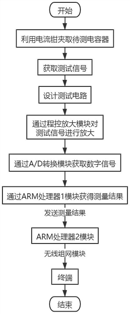
[0027] refer to Figure 1 ~ Figure 2 , which is the first embodiment of the present invention, this embodiment provides a wireless measurement method for capacitors, including:

[0028] S1: Use the current clamp to clamp the capacitor under test to obtain the test signal.

[0029] Preferably, in order to reduce the workload of the measurement process, the method adopts the current clamp method for detection; the current clamp can detect the current flowing through a single capacitor, and calculate the voltage by using the voltage detected on the capacitor and the current sampled by the current clamp. capacity.

[0030] S2: Design the test circuit.

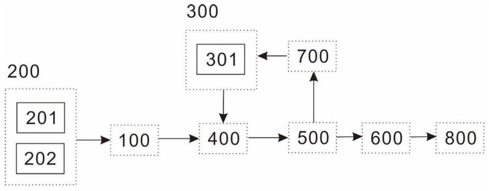
[0031] refer to figure 2 , the test circuit includes a programmable amplifier module 100, a signal input protection module 200, a voltage divider module 300, an A / D conversion module 400, an ARM processor 1 module 500, an ARM processor 2 module 600, a power amplifier module 700 and a wireless networking module 800 .

[0032] ...

Embodiment 2

[0050] The technical effect adopted in this method is verified and explained. This embodiment chooses the traditional technical solution and adopts this method to conduct a comparative test, and compares the test results by means of scientific demonstration to verify the real effect of this method.

[0051] When testing a single capacitor of the compensation capacitor bank, the traditional technical solution needs to remove the capacitor leads and test one by one. The test data needs to be recorded by hand and cannot be collected automatically.

[0052] In order to verify that this method does not need to remove the capacitor lead when testing the single capacitance of the compensation capacitor group compared with the traditional technical solution, it can complete the single and total capacitance test and realize wireless automatic collection of test data.

[0053] In this embodiment, the traditional technical solution and this method will be used to test the capacitance of t...


PUM


Abstract

The invention discloses a wireless measurement method for a capacitor. The method comprises the steps of clamping a to-be-measured capacitor through a current clamp, and obtaining a test signal, designing a test circuit, amplifying a test signal through a program control amplification module in the test circuit, and converting the amplified test signal through an A / D conversion module in the test circuit to obtain a digital signal, according to the digital signal, acquiring a measurement result through an ARM processor 1 module in the test circuit, and transmitting the measurement result to an ARM processor 2 module in the test circuit, enabling the ARM processor 2 module to communicate with a wireless networking module in the test circuit through a serial port protocol, and transmitting a measurement result to a terminal through the wireless networking module. Through designing the test circuit, damage to the capacitor porcelain bushing caused by lead removal is avoided, the test efficiency is improved, and the labor intensity is reduced; wireless collection of test data is achieved, and management and analysis of the test data are facilitated.

Description

technical field [0001] The invention relates to the technical field of power testing, in particular to a wireless measuring method for capacitors. Background technique [0002] In the power system, in order to improve the power factor, it is necessary to use a large number of reactive power compensation capacitors. Ensuring the normal and stable operation of capacitors is of great significance to maintaining the stability of the power grid; due to the large number of capacitors and the high installation position, the workload of measurement and data collection is heavy. [0003] At present, the capacitor leads need to be removed for the compensation capacitor test, and the capacitors are tested one by one. The test efficiency is low and the workload is heavy; and the data cannot be collected wirelessly. Contents of the invention [0004] The purpose of this section is to outline some aspects of embodiments of the invention and briefly describe some preferred embodiments. ...

Claims


Application Information

Patent Timeline
Patent Type & Authority Applications(China)
IPC IPC(8): G01R31/01G01R1/04G05B19/042G08C17/02
CPCG01R31/016G01R1/0408G05B19/0423G08C17/02
Inventor 陈家辉何维田维国任飞高宇吴明豪肖力程伟周仲波
Owner GUIZHOU POWER GRID CO LTD
Why Eureka
Try Eureka