
Thin film transistor device, backlight module and display panel

A technology of thin-film transistors and backlight modules, which is applied in the direction of transistors, semiconductor devices, and electric solid-state devices. The effect of the transmission path

Active Publication Date: 2021-08-24
HUIZHOU CHINA STAR OPTOELECTRONICS TECHNOLOGY CO LTD +1
View PDF4 Cites 0 Cited by
  • Summary
  • Abstract
  • Description
  • Claims
  • Application Information

AI Technical Summary

Problems solved by technology

[0005] The purpose of the present invention is to provide a thin film transistor device, a backlight module and a display panel, which solves the problem in the prior art that the driving current of the Mini LED is small, resulting in a low backlight intensity of the Mini LED backplane

Method used


Image

  • Thin film transistor device, backlight module and display panel
  • Thin film transistor device, backlight module and display panel
  • Thin film transistor device, backlight module and display panel

Examples


Embodiment Construction

[0034] The technical solutions in the embodiments of the present invention will be clearly and completely described below in conjunction with the drawings in the embodiments of the present invention. Apparently, the described embodiments are only some of the embodiments of the present invention, but not all of them. Based on the embodiments of the present invention, all other embodiments obtained by those skilled in the art without creative efforts fall within the protection scope of the present invention. In the description of the present invention, it should be understood that the orientation or positional relationship indicated by the terms "upper", "lower", "near" etc. is based on the orientation or positional relationship shown in the drawings, for example, "upper" is only a superficial Above the object, it can specifically refer to directly above, obliquely above, or the upper surface, as long as it is above the level of the object; "both sides" refer to the two relative...


PUM


Abstract

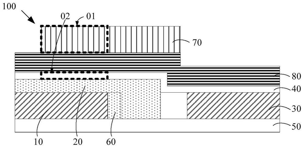
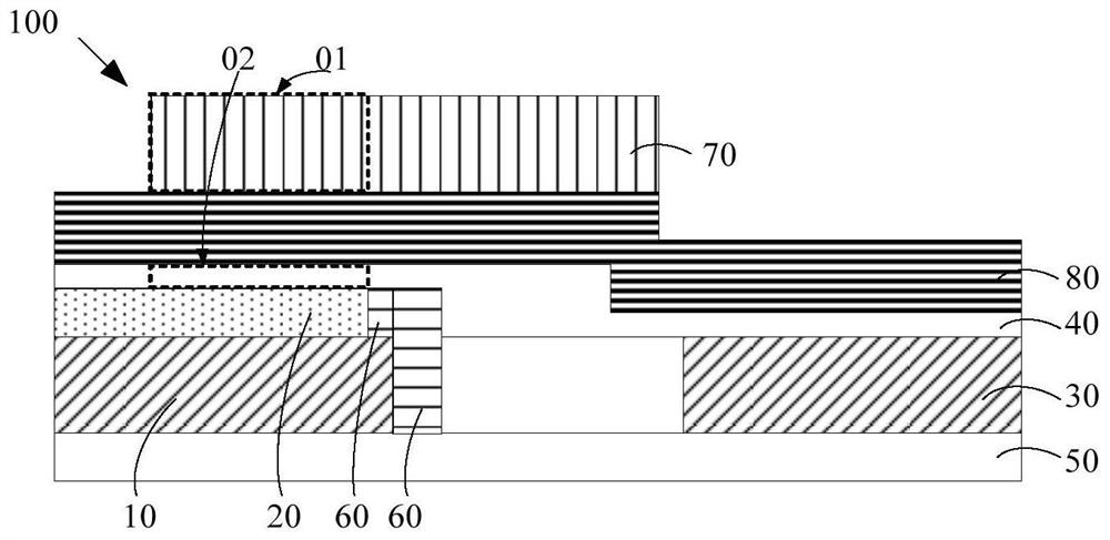
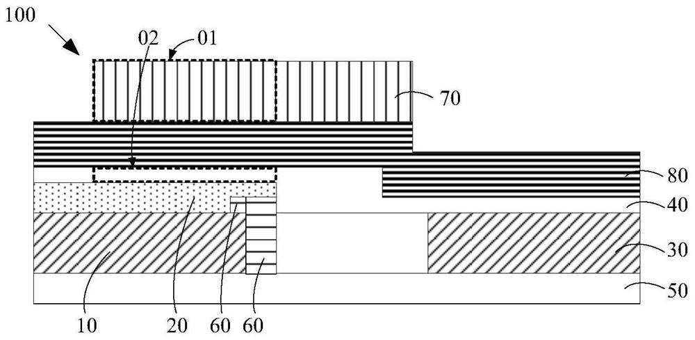
The invention provides a thin film transistor device, a backlight module and a display panel. The thin film transistor device comprises a source electrode part, an active layer located on the source electrode part, a drain electrode part separated from the source electrode part, and a conductor part located on the active layer and extending to the drain electrode part, according to the invention, the active layer is arranged on the source electrode part, and the drain electrode part and the active layer are electrically connected through the conductor part, so that the current can be transmitted to the active layer from the drain electrode part through the conductor part, and further, the current is transmitted to the source electrode part along the thickness direction of the active layer, thereby shortening the transmission path of the current, increasing the driving current of the thin film transistor device, and improving the backlight intensity of the backlight module and the luminous intensity of the display panel.

Description

technical field [0001] The invention relates to the field of display technology, in particular to a thin film transistor device, a backlight module and a display panel. Background technique [0002] Compared with the traditional LED (Light-Emitting Diode, light-emitting diode) backlight, the Mini LED (Mini Light-Emitting Diode, light-emitting diode) backlight can achieve a million-level contrast ratio to improve display quality. [0003] At present, the Mini LED backplane is driven by current, but the thin-film transistor device used to drive the Mini LED is limited by mobility, stability, or process accuracy. The final output current of the thin-film transistor device is low, which makes it impossible for the Mini LED to obtain a large enough The drive current reduces the backlight intensity of the Mini LED backplane. [0004] Therefore, it is necessary to provide a thin film transistor device, a backlight module and a display panel that can increase the driving current of...

Claims


Application Information

Patent Timeline
Patent Type & Authority Applications(China)
IPC IPC(8): H01L29/10H01L29/786H01L27/12H01L27/15
CPCH01L29/78696H01L29/1033H01L27/1222H01L27/153H01L27/156G02F1/133603G02F1/133612H01L29/41733H01L29/78633
Inventor 胡道兵
Owner HUIZHOU CHINA STAR OPTOELECTRONICS TECHNOLOGY CO LTD
Learn More