
Hollow waveguide cavity for enhancing gas Raman signal

A Raman signal and waveguide cavity technology, which is applied in Raman scattering, material excitation analysis, instruments, etc., can solve the problems of poor optical stability, low detection limit, and short detection time of resonant cavity technology, and achieve fast Raman spectroscopy The effects of detection, improved speed of entry and exit, and improvement of mechanical strength

Inactive Publication Date: 2021-08-24
CHONGQING UNIV
View PDF0 Cites 0 Cited by
  • Summary
  • Abstract
  • Description
  • Claims
  • Application Information

AI Technical Summary

Problems solved by technology

Among them, the resonant cavity can make the laser reflect nearly infinite times in the cavity, and it can greatly enhance the gas Raman signal, and the detection limit is relatively low, but the anti-interference ability of the frequency locking technology necessary for the resonant cavity is low, resulting in The optical stability of the technology is poor; the anti-interference ability of the multi-anti-cavity is strong, and the optical stability is strong, but due to the limited number of reflections of the laser in the cavity, the enhancement of the Raman signal is low, and the detection limit of the multi-component gas is still relatively low. high
[0007] Therefore, the current gas Raman signal enhancement methods are difficult to balance high efficiency enhancement, high stability, high repeatability, and short detection time.

Method used


Image

  • Hollow waveguide cavity for enhancing gas Raman signal
  • Hollow waveguide cavity for enhancing gas Raman signal
  • Hollow waveguide cavity for enhancing gas Raman signal

Examples


Embodiment 1

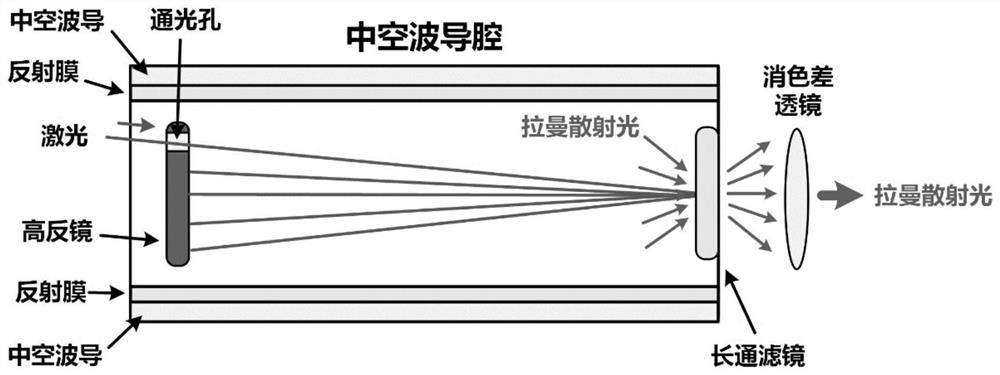
[0060] The hollow waveguide is a hollow tube made of silica, with a length of 0.5 m, an outer diameter of 35 mm, and an inner diameter of 28 mm.

[0061] The high reflection mirror is a circular plano-concave mirror with a diameter of 25 mm, a concave reflective surface, and a radius of curvature of 0.5 m.

[0062] The high reflection mirror has a light hole through which the laser enters the hollow waveguide cavity. The diameter of the light hole is 3mm, and the distance from the center of the light hole to the center of the high reflection mirror is 20mm.

[0063] The long-pass filter is a circular plane mirror with a diameter of 25mm, which sets the cut-off wavelength of the light wave according to the laser wavelength. For example, if the laser wavelength is 532nm, the cut-off wavelength is 533nm.

[0064] The achromatic lens is a circular biconvex lens with a diameter of 25mm and a focal length of 0.5m for light of 500nm-700nm.

[0065] Such as figure 2 As shown, the e...


PUM

PropertyMeasurementUnit
lengthaaaaaaaaaa
diameteraaaaaaaaaa
reflectanceaaaaaaaaaa

Abstract

The invention discloses a hollow waveguide cavity for enhancing a gas Raman signal. The hollow waveguide cavity comprises a hollow waveguide, a high-reflectivity mirror, a long-pass filter and an achromatic lens, the hollow waveguide forms a hollow waveguide cavity, and the inner wall of the hollow waveguide is coated with a reflecting film; the high-reflectivity mirror and the long-pass filter are respectively arranged at the head end and the tail end of the hollow waveguide cavity; the hollow waveguide cavity is filled with to-be-detected gas, and laser is incident into the hollow waveguide cavity from the high-reflectivity mirror and excites Raman scattering light of the to-be-detected gas; raman scattering light propagating along different directions in the cavity of the hollow waveguide is reflected for multiple times among the high-reflectivity mirror, the long-pass filter and the reflecting film on the inner wall of the hollow waveguide, and is emitted after being filtered by the long-pass filter; and raman scattering light transmitted by the long-pass filter is collimated by the achromatic lens to obtain a gas Raman signal enhanced by the hollow waveguide cavity. According to the invention, improvement of Raman signal collection efficiency by an optical fiber enhancement technology and extension of an effective laser path by a cavity enhancement technology are fused, so that a relatively low Raman spectrum gas detection limit is realized.

Description

technical field [0001] The invention belongs to the technical field of gas Raman spectrum detection, and relates to a hollow waveguide cavity for gas Raman signal enhancement. Background technique [0002] Gas detection has a wide range of needs in environmental pollution detection, safety gas monitoring, industrial process control and other fields. Raman spectroscopy gas detection method is based on the Raman effect of gas. It judges the gas composition by measuring the wavelength of the Raman scattered light generated by the gas due to laser irradiation, and judges the gas content by measuring the scattered light intensity. A spectral gas detection method. [0003] Compared with the current commonly used gas detection methods, Raman spectroscopy has the following advantages: it can detect almost all gas components at the same time; different gas components have little interference with each other and high detection selectivity; . Therefore, Raman spectroscopy has great a...

Claims


Application Information

Patent Timeline
Patent Type & Authority Applications(China)
IPC IPC(8): G01N21/65
CPCG01N21/658
Inventor 王品一陈伟根王建新万福王有元杜林周湶李剑
Owner CHONGQING UNIV
Learn More