Volumetric solar cavity heat absorber with rotary heat absorbing body

A heat absorber and volumetric technology, which is applied in the field of solar heat absorbers and volumetric solar cavity heat absorbers, can solve problems such as uneven distribution of radiant energy, limited number of heat exchange contacts, thermal stress damage of heat absorbers, etc. , to achieve uniform temperature distribution, low cost, and enhanced convective heat transfer intensity

Inactive Publication Date: 2021-08-24
HUNAN UNIV OF SCI & TECH
View PDF8 Cites 2 Cited by
  • Summary
  • Abstract
  • Description
  • Claims
  • Application Information

AI Technical Summary

Problems solved by technology

Due to the extremely uneven distribution of radiant energy collected on the heat absorber in the solar concentrating heat collection system during actual operation, and the working fluid usually flows in from one side of the heat absorber and immediately flows out from the other side, the entire heat exchange contact The number of times is limited; and with the dual effects of flow resistance and temperature difference (working fluid and heat absorber) along the way, the heat transfer intensity near the outlet side decreases significantly, especially for high heat flow areas. If the heat exchange is not timely, the heat absorber will The high temperature difference and high temperature hot spots will easily cause thermal stress damage and thermal ablation of the heat absorber.

Method used


Image

  • Volumetric solar cavity heat absorber with rotary heat absorbing body
  • Volumetric solar cavity heat absorber with rotary heat absorbing body

Examples


Embodiment Construction

[0017] The present invention will be further described below in conjunction with the accompanying drawings.

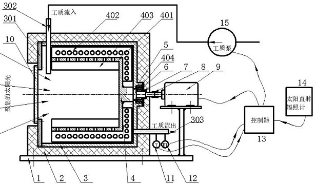
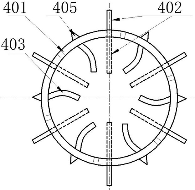
[0018] Such as figure 1 As shown, the present invention includes an outer cylindrical body 3 with an axisymmetric cavity structure and a through hole is opened on its front end plate 301, a heat absorber 4 located in the outer cylindrical body 3 and coaxially arranged with the outer cylindrical body 3, and an installation The opening position of the front end plate 301 is used to seal the glass cover plate 10 of the outer cylinder 3, and the insulation layer 2 wrapped on the outside of the outer cylinder 3 for heat insulation, and the working fluid communicating with the inner cavity of the outer cylinder 3 flows into the Pipe 303 and working fluid outflow pipe 302; the heat absorbing body 4 is composed of a heat absorbing main body 401 with a concave cavity structure with an opening on one side, a plurality of heat absorbing bodies 401 along the outer surface of the h...


PUM


Abstract

The invention discloses a volumetric solar cavity heat absorber with a rotary heat absorbing body. The volumetric solar cavity heat absorber is composed of an outer barrel, the heat absorbing body, a glass cover plate, a motor, a controller, a temperature sensor and the like, wherein the heat absorbing body is composed of a heat absorbing main body in a concave cavity shape, a plurality of outer fins arranged on the outer side surface and the outer bottom surface of the heat absorbing main body, a plurality of inner fins arranged on the inner side surface of the heat absorbing main body and a transmission shaft arranged at the bottom of the heat absorbing main body; the inner surface of a concave cavity of the heat absorbing main body absorbs sunlight; a plurality of through holes are formed in the side wall and the bottom of the heat absorbing main body and the outer fins; and the transmission shaft is matched with a stepped hole in the bottom of the outer barrel through the shaft surface of the transmission shaft and an installed bearing, and the tail end of the transmission shaft is fixedly connected with an output shaft of the motor through a connecting sleeve. The motor is controlled to drive the heat absorbing body to rotate, so that the convective heat exchange intensity of the heat absorbing body and a heat transfer working medium is improved, the working temperature distribution of the heat absorbing body and the distribution uniformity of absorbed solar energy are improved, and safe, reliable and efficient operation of the solar heat absorber achieved.

Description

technical field [0001] The invention belongs to the field of solar energy concentrating heat collection and utilization, and relates to a solar heat absorber, in particular to a volumetric solar cavity heat absorber in which a heat absorbing body rotates. Background technique [0002] Solar energy is a clean, environmentally friendly and widely distributed renewable energy. The development and utilization of solar energy for high-temperature heating or thermal power generation is one of the important ways to achieve sustainable human development. The realization of the above technology usually uses a concentrator composed of large-area reflectors to gather low-density sunlight into a small cavity heat absorber, and is absorbed by the heat absorber in the heat absorber, thereby generating high temperature to heat The heat transfer medium realizes the conversion of solar light energy into the heat energy of the working medium; then, through these heat working medium, external ...

Claims


Application Information

Patent Timeline
Patent Type & Authority Applications(China)
IPC IPC(8): F24S10/70F24S50/40
CPCF24S10/70F24S50/40Y02E10/44
Inventor 颜健刘永祥田勇聂笃忠
Owner HUNAN UNIV OF SCI & TECH
Why Eureka
Try Eureka