
Pulse power supply system and neutron generator

A technology of pulse power supply and pulse transformer, which is applied in the direction of electric pulse generator circuit, DC voltage accelerator, and energy storage components to generate pulses, etc., which can solve the problem of larger occupied space, unable to meet the application requirements of well logging neutron generators, and small power supply Difficulties and other issues

Active Publication Date: 2021-08-20
中科石金(安徽)中子技术有限公司
View PDF5 Cites 2 Cited by
  • Summary
  • Abstract
  • Description
  • Claims
  • Application Information

AI Technical Summary

Problems solved by technology

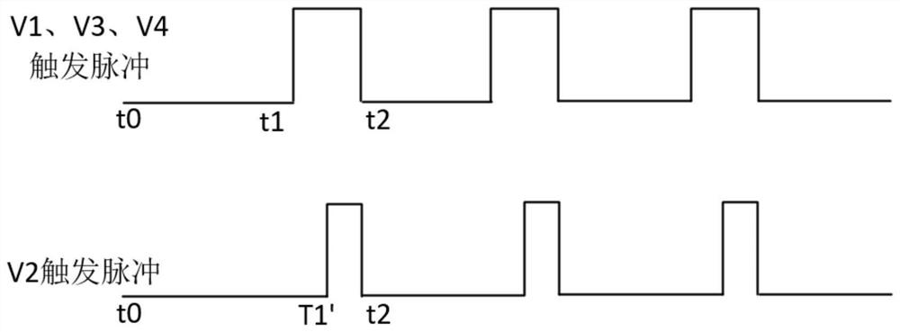
Trigger pulse high voltage, main arc discharge pulse high voltage and acceleration pulse high voltage are all different in amplitude, pulse width and timing. The existing technology uses several pulse power supplies to supply power independently, which makes it very difficult to miniaturize the power supply and cannot meet the application of well logging neutron generators need
[0004] Vacuum arc ion source neutron generators can be divided into cathode grounding and cathode connection positive high voltage according to the potential of the cathode. Compared with cathode grounding, the insulation distance between the accelerating electrode and the ground potential can be The diameter of the neutron generator is reduced by half, but since the anode voltage and trigger voltage are suspended above the cathode voltage at this time, it is necessary to set up a corresponding isolation transformer, which makes the system more complicated and takes up more space. , not conducive to miniaturization

Method used


Image

  • Pulse power supply system and neutron generator
  • Pulse power supply system and neutron generator
  • Pulse power supply system and neutron generator

Examples


Embodiment 1

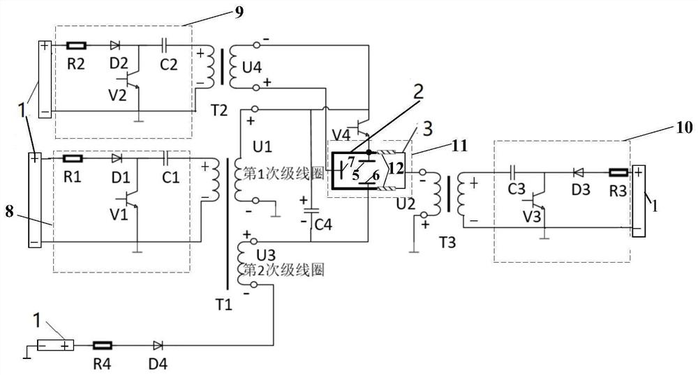
[0040] Such as figure 1 as shown, figure 1 A basic circuit diagram of a pulse power supply system provided by an embodiment of the present invention, the pulse power supply system includes a charging power supply 1, a first pulse forming circuit 8 connected to the charging power supply 1, a second pulse forming circuit 9 and a third pulse forming circuit 10 , also includes the first step-up pulse transformer T1, the second step-up pulse transformer T2, the third step-up pulse transformer T3, the vacuum arc ion source 11, the fourth discharge switch V4 and the main discharge capacitor C4;

[0041] The first pulse forming circuit 8 is connected to the primary coil of the first step-up pulse transformer T1; the high potential of the first secondary coil of the first step-up pulse transformer T1 is connected to the positive pole of the main discharge capacitor C4, and the first booster The high potential of the first secondary coil of the voltage pulse transformer T1 is also conn...

Embodiment 2

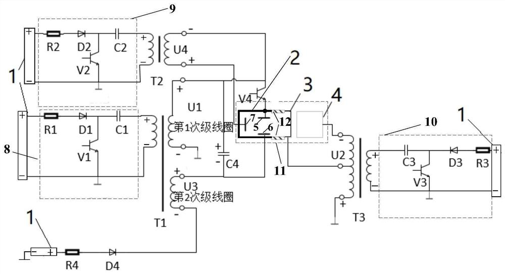
[0077] Such as image 3 as shown, image 3 The basic circuit diagram of another pulse power supply system provided for the embodiment of the present invention, the third step-up pulse transformer T3 in Embodiment 1 is a single tap, the high potential of the secondary coil is grounded, and the low potential of the secondary coil is connected to the vacuum arc The negative accelerating pole 3 of the ion source is connected; compared with embodiment 1, the third step-up pulse transformer T3 in the present embodiment is a double tap, the high potential of the secondary coil is grounded, and the middle tap of the secondary coil is connected to the vacuum arc ion The negative accelerating pole 3 of the source 11 and the low potential tap of the secondary coil are connected to the extraction pole 4 of the vacuum arc ion source 11, wherein the positive accelerating pole 2 and the negative accelerating pole 3 are insulated by an insulator.

[0078] The ratio of the double-tap third st...


PUM


Abstract

The invention relates to a pulse power supply system and a neutron generator. Several paths of pulse voltages with different pulse widths and amplitudes can be provided for the neutron generator through four paths of pulse voltages, namely positive acceleration high voltage, negative acceleration high voltage, anode voltage and trigger voltage, so as to meet the working requirements of a vacuum arc ion source neutron generator. The positive acceleration high voltage is generated through the first secondary coil of a first pulse transformer T1, the trigger voltage is generated through a second pulse transformer T2, the anode voltage is generated through the second secondary coil of a first pulse transformer T1 and a main discharge capacitor C4, and the negative acceleration high voltage is generated through a third pulse transformer T3. The second secondary coil of the first pulse transformer T1 and the second pulse transformer T2 serve as a boosting transformer to boost a pulse power supply and also serve as an isolation transformer to solve the problem of suspension voltage, the insulation distance is effectively reduced by adopting a positive and negative acceleration pole structure, and three pulses form a loop to share one charging power supply, so the power supply system is very compact in structure.

Description

technical field [0001] The invention relates to the technical field of neutron generators, in particular to a pulse power supply system and a neutron generator. Background technique [0002] As a neutron source for small accelerators, neutron generators have many advantages such as portability, mobility, safety in use, and no radiation hazards, and have been widely used in oil and gas well logging. In order to meet the needs of logging in deeper formations, neutron generators are required to have smaller diameters and higher temperature resistance. The ion source of the neutron generator generally includes a Penning ion source and a vacuum arc ion source. The vacuum arc ion source is composed of a cathode, an anode, and a trigger electrode. [0003] When the vacuum arc ion source neutron generator is working, a pulse high voltage with an amplitude of about 10kV and a pulse width of several μs is firstly applied between the trigger electrode and the cathode to generate initi...

Claims


Application Information

Patent Timeline
Patent Type & Authority Applications(China)
IPC IPC(8): H02M9/00H02M9/04H03K3/57H05H3/06
CPCH02M11/00H03K3/57H05H3/06
Inventor 不公告发明人
Owner 中科石金(安徽)中子技术有限公司
Learn More